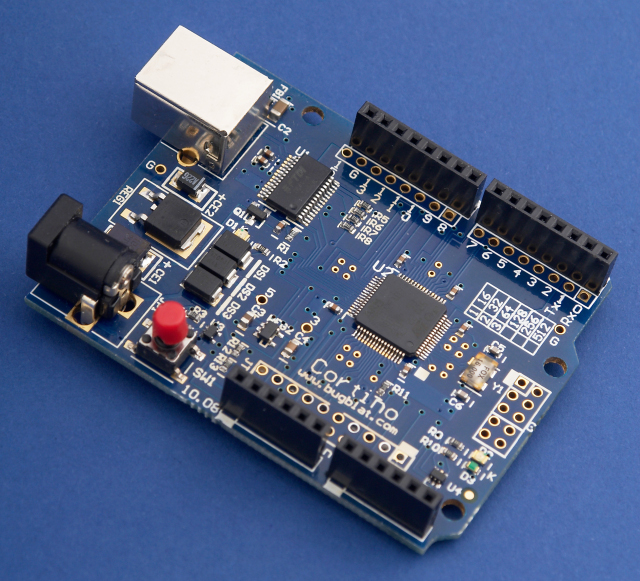
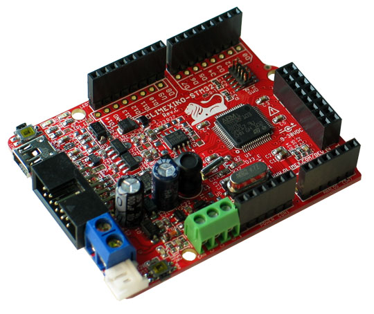
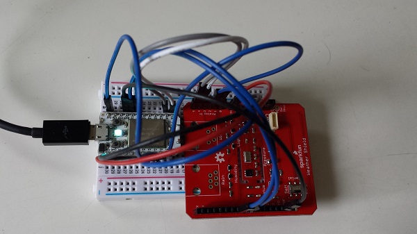
In my previous blog post I described my first encounter with the Spark Core. Today I want to demonstrate a first simple code example. For this I connected the Spark Core to a Weather Shield from Sparkfun. The shield offers sensors for light, humidity, temperature and pressure. It can even be extended with rain and wind sensors as well as GPS.
.
The shield comes with a nice set of libraries and examples that I used as a starting point. To keep things really simple, I combine the entire Weather Shield source with the sensor library functions and the setup() and loop() into a single file. This did not take long and compiled quickly. I also removed the wind and rain related functionality as I did not plan to use those. The source code below takes measurements every second and writes the them to the USB serial port.
/*
MPL3115A2 Barometric Pressure Sensor Library
By: Nathan Seidle
SparkFun Electronics
Date: September 22nd, 2013
License: This code is public domain but you buy me a beer if you use this and we meet someday (Beerware license).
This library allows an Arduino to read from the MPL3115A2 low-cost high-precision pressure sensor.
If you have feature suggestions or need support please use the github support page: https://github.com/sparkfun/MPL3115A2_Breakout
Hardware Setup: The MPL3115A2 lives on the I2C bus. Attach the SDA pin to A4, SCL to A5. Use inline 10k resistors
if you have a 5V board. If you are using the SparkFun breakout board you *do not* need 4.7k pull-up resistors
on the bus (they are built-in).
Link to the breakout board product:
Software:
.begin() Gets sensor on the I2C bus.
.readAltitude() Returns float with meters above sealevel. Ex: 1638.94
.readAltitudeFt() Returns float with feet above sealevel. Ex: 5376.68
.readPressure() Returns float with barometric pressure in Pa. Ex: 83351.25
.readTemp() Returns float with current temperature in Celsius. Ex: 23.37
.readTempF() Returns float with current temperature in Fahrenheit. Ex: 73.96
.setModeBarometer() Puts the sensor into Pascal measurement mode.
.setModeAltimeter() Puts the sensor into altimetery mode.
.setModeStandy() Puts the sensor into Standby mode. Required when changing CTRL1 register.
.setModeActive() Start taking measurements!
.setOversampleRate(byte) Sets the # of samples from 1 to 128. See datasheet.
.enableEventFlags() Sets the fundamental event flags. Required during setup.
*/
/*******************************************************************************************/
//#include "MPL3115A2.h"
/*******************************************************************************************/
#define MPL3115A2_ADDRESS 0x60 // Unshifted 7-bit I2C address for sensor
#define STATUS 0x00
#define OUT_P_MSB 0x01
#define OUT_P_CSB 0x02
#define OUT_P_LSB 0x03
#define OUT_T_MSB 0x04
#define OUT_T_LSB 0x05
#define DR_STATUS 0x06
#define OUT_P_DELTA_MSB 0x07
#define OUT_P_DELTA_CSB 0x08
#define OUT_P_DELTA_LSB 0x09
#define OUT_T_DELTA_MSB 0x0A
#define OUT_T_DELTA_LSB 0x0B
#define WHO_AM_I 0x0C
#define F_STATUS 0x0D
#define F_DATA 0x0E
#define F_SETUP 0x0F
#define TIME_DLY 0x10
#define SYSMOD 0x11
#define INT_SOURCE 0x12
#define PT_DATA_CFG 0x13
#define BAR_IN_MSB 0x14
#define BAR_IN_LSB 0x15
#define P_TGT_MSB 0x16
#define P_TGT_LSB 0x17
#define T_TGT 0x18
#define P_WND_MSB 0x19
#define P_WND_LSB 0x1A
#define T_WND 0x1B
#define P_MIN_MSB 0x1C
#define P_MIN_CSB 0x1D
#define P_MIN_LSB 0x1E
#define T_MIN_MSB 0x1F
#define T_MIN_LSB 0x20
#define P_MAX_MSB 0x21
#define P_MAX_CSB 0x22
#define P_MAX_LSB 0x23
#define T_MAX_MSB 0x24
#define T_MAX_LSB 0x25
#define CTRL_REG1 0x26
#define CTRL_REG2 0x27
#define CTRL_REG3 0x28
#define CTRL_REG4 0x29
#define CTRL_REG5 0x2A
#define OFF_P 0x2B
#define OFF_T 0x2C
#define OFF_H 0x2D
class MPL3115A2 {
public:
MPL3115A2();
//Public Functions
bool begin(); // Gets sensor on the I2C bus.
float readAltitude(); // Returns float with meters above sealevel. Ex: 1638.94
float readAltitudeFt(); // Returns float with feet above sealevel. Ex: 5376.68
float readPressure(); // Returns float with barometric pressure in Pa. Ex: 83351.25
float readTemperature(); // Returns float with current temperature in Celsius. Ex: 23.37
float readTemperatureF(); // Returns float with current temperature in Fahrenheit. Ex: 73.96
void setModeBarometer(); // Puts the sensor into Pascal measurement mode.
void setModeAltimeter(); // Puts the sensor into altimetery mode.
void setModeStandby(); // Puts the sensor into Standby mode. Required when changing CTRL1 register.
void setModeActive(); // Start taking measurements!
void setOversampleRate(byte); // Sets the # of samples from 1 to 128. See datasheet.
void enableEventFlags(); // Sets the fundamental event flags. Required during setup.
//Public Variables
private:
//Private Functions
void toggleOneShot();
byte IIC_Read(byte regAddr);
void IIC_Write(byte regAddr, byte value);
//Private Variables
};
/*******************************************************************************************/
MPL3115A2::MPL3115A2()
{
//Set initial values for private vars
}
//Begin
/*******************************************************************************************/
//Start I2C communication
bool MPL3115A2::begin(void)
{
Wire.begin();
}
//Returns the number of meters above sea level
//Returns -1 if no new data is available
float MPL3115A2::readAltitude()
{
toggleOneShot(); //Toggle the OST bit causing the sensor to immediately take another reading
//Wait for PDR bit, indicates we have new pressure data
int counter = 0;
while( (IIC_Read(STATUS) & (1<<1)) == 0)
{
if(++counter > 600) return(-999); //Error out after max of 512ms for a read
delay(1);
}
// Read pressure registers
Wire.beginTransmission(MPL3115A2_ADDRESS);
Wire.write(OUT_P_MSB); // Address of data to get
Wire.endTransmission(false); // Send data to I2C dev with option for a repeated start. THIS IS NECESSARY and not supported before Arduino V1.0.1!
Wire.requestFrom(MPL3115A2_ADDRESS, 3); // Request three bytes
//Wait for data to become available
counter = 0;
while(Wire.available() < 3)
{
if(counter++ > 100) return(-999); //Error out
delay(1);
}
byte msb, csb, lsb;
msb = Wire.read();
csb = Wire.read();
lsb = Wire.read();
// The least significant bytes l_altitude and l_temp are 4-bit,
// fractional values, so you must cast the calulation in (float),
// shift the value over 4 spots to the right and divide by 16 (since
// there are 16 values in 4-bits).
float tempcsb = (lsb>>4)/16.0;
float altitude = (float)( (msb << 8) | csb) + tempcsb;
return(altitude);
}
//Returns the number of feet above sea level
float MPL3115A2::readAltitudeFt()
{
return(readAltitude() * 3.28084);
}
//Reads the current pressure in Pa
//Unit must be set in barometric pressure mode
//Returns -1 if no new data is available
float MPL3115A2::readPressure()
{
//Check PDR bit, if it's not set then toggle OST
if(IIC_Read(STATUS) & (1<<2) == 0) toggleOneShot(); //Toggle the OST bit causing the sensor to immediately take another reading
//Wait for PDR bit, indicates we have new pressure data
int counter = 0;
while(IIC_Read(STATUS) & (1<<2) == 0)
{
if(++counter > 600) return(-999); //Error out after max of 512ms for a read
delay(1);
}
// Read pressure registers
Wire.beginTransmission(MPL3115A2_ADDRESS);
Wire.write(OUT_P_MSB); // Address of data to get
Wire.endTransmission(false); // Send data to I2C dev with option for a repeated start. THIS IS NECESSARY and not supported before Arduino V1.0.1!
Wire.requestFrom(MPL3115A2_ADDRESS, 3); // Request three bytes
//Wait for data to become available
counter = 0;
while(Wire.available() < 3)
{
if(counter++ > 100) return(-999); //Error out
delay(1);
}
byte msb, csb, lsb;
msb = Wire.read();
csb = Wire.read();
lsb = Wire.read();
toggleOneShot(); //Toggle the OST bit causing the sensor to immediately take another reading
// Pressure comes back as a left shifted 20 bit number
long pressure_whole = (long)msb<<16 | (long)csb<<8 | (long)lsb;
pressure_whole >>= 6; //Pressure is an 18 bit number with 2 bits of decimal. Get rid of decimal portion.
lsb &= 0b00110000; //Bits 5/4 represent the fractional component
lsb >>= 4; //Get it right aligned
float pressure_decimal = (float)lsb/4.0; //Turn it into fraction
float pressure = (float)pressure_whole + pressure_decimal;
return(pressure);
}
float MPL3115A2::readTemperature()
{
if(IIC_Read(STATUS) & (1<<1) == 0) toggleOneShot(); //Toggle the OST bit causing the sensor to immediately take another reading
//Wait for TDR bit, indicates we have new temp data
int counter = 0;
while( (IIC_Read(STATUS) & (1<<1)) == 0)
{
if(++counter > 600) return(-999); //Error out after max of 512ms for a read
delay(1);
}
// Read temperature registers
Wire.beginTransmission(MPL3115A2_ADDRESS);
Wire.write(OUT_T_MSB); // Address of data to get
Wire.endTransmission(false); // Send data to I2C dev with option for a repeated start. THIS IS NECESSARY and not supported before Arduino V1.0.1!
Wire.requestFrom(MPL3115A2_ADDRESS, 2); // Request two bytes
//Wait for data to become available
counter = 0;
while(Wire.available() < 2)
{
if(counter++ > 100) return(-999); //Error out
delay(1);
}
byte msb, lsb;
msb = Wire.read();
lsb = Wire.read();
toggleOneShot(); //Toggle the OST bit causing the sensor to immediately take another reading
//Negative temperature fix by D.D.G.
short foo = 0;
bool negSign = false;
//Check for 2s compliment
if(msb > 0x7F)
{
foo = ~((msb << 8) + lsb) + 1; //2’s complement
msb = foo >> 8;
lsb = foo & 0x00F0;
negSign = true;
}
// The least significant bytes l_altitude and l_temp are 4-bit,
// fractional values, so you must cast the calulation in (float),
// shift the value over 4 spots to the right and divide by 16 (since
// there are 16 values in 4-bits).
float templsb = (lsb>>4)/16.0; //temp, fraction of a degree
float temperature = (float)(msb + templsb);
if (negSign) temperature = 0 - temperature;
return(temperature);
}
//Give me temperature in fahrenheit!
float MPL3115A2::readTemperatureF()
{
return((readTemperature() * 9.0)/ 5.0 + 32.0); // Convert celsius to fahrenheit
}
//Sets the mode to Barometer
//CTRL_REG1, ALT bit
void MPL3115A2::setModeBarometer()
{
byte tempSetting = IIC_Read(CTRL_REG1); //Read current settings
tempSetting &= ~(1<<7); //Clear ALT bit
IIC_Write(CTRL_REG1, tempSetting);
}
//Sets the mode to Altimeter
//CTRL_REG1, ALT bit
void MPL3115A2::setModeAltimeter()
{
byte tempSetting = IIC_Read(CTRL_REG1); //Read current settings
tempSetting |= (1<<7); //Set ALT bit
IIC_Write(CTRL_REG1, tempSetting);
}
//Puts the sensor in standby mode
//This is needed so that we can modify the major control registers
void MPL3115A2::setModeStandby()
{
byte tempSetting = IIC_Read(CTRL_REG1); //Read current settings
tempSetting &= ~(1<<0); //Clear SBYB bit for Standby mode
IIC_Write(CTRL_REG1, tempSetting);
}
//Puts the sensor in active mode
//This is needed so that we can modify the major control registers
void MPL3115A2::setModeActive()
{
byte tempSetting = IIC_Read(CTRL_REG1); //Read current settings
tempSetting |= (1<<0); //Set SBYB bit for Active mode
IIC_Write(CTRL_REG1, tempSetting);
}
//Call with a rate from 0 to 7. See page 33 for table of ratios.
//Sets the over sample rate. Datasheet calls for 128 but you can set it
//from 1 to 128 samples. The higher the oversample rate the greater
//the time between data samples.
void MPL3115A2::setOversampleRate(byte sampleRate)
{
if(sampleRate > 7) sampleRate = 7; //OS cannot be larger than 0b.0111
sampleRate <<= 3; //Align it for the CTRL_REG1 register
byte tempSetting = IIC_Read(CTRL_REG1); //Read current settings
tempSetting &= 0b11000111; //Clear out old OS bits
tempSetting |= sampleRate; //Mask in new OS bits
IIC_Write(CTRL_REG1, tempSetting);
}
//Enables the pressure and temp measurement event flags so that we can
//test against them. This is recommended in datasheet during setup.
void MPL3115A2::enableEventFlags()
{
IIC_Write(PT_DATA_CFG, 0x07); // Enable all three pressure and temp event flags
}
//Clears then sets the OST bit which causes the sensor to immediately take another reading
//Needed to sample faster than 1Hz
void MPL3115A2::toggleOneShot(void)
{
byte tempSetting = IIC_Read(CTRL_REG1); //Read current settings
tempSetting &= ~(1<<1); //Clear OST bit
IIC_Write(CTRL_REG1, tempSetting);
tempSetting = IIC_Read(CTRL_REG1); //Read current settings to be safe
tempSetting |= (1<<1); //Set OST bit
IIC_Write(CTRL_REG1, tempSetting);
}
// These are the two I2C functions in this sketch.
byte MPL3115A2::IIC_Read(byte regAddr)
{
// This function reads one byte over IIC
Wire.beginTransmission(MPL3115A2_ADDRESS);
Wire.write(regAddr); // Address of CTRL_REG1
Wire.endTransmission(false); // Send data to I2C dev with option for a repeated start. THIS IS NECESSARY and not supported before Arduino V1.0.1!
Wire.requestFrom(MPL3115A2_ADDRESS, 1); // Request the data...
return Wire.read();
}
void MPL3115A2::IIC_Write(byte regAddr, byte value)
{
// This function writes one byto over IIC
Wire.beginTransmission(MPL3115A2_ADDRESS);
Wire.write(regAddr);
Wire.write(value);
Wire.endTransmission(true);
}
/*
HTU21D Humidity Sensor Library
By: Nathan Seidle
SparkFun Electronics
Date: September 22nd, 2013
License: This code is public domain but you buy me a beer if you use this and we meet someday (Beerware license).
This library allows an Arduino to read from the HTU21D low-cost high-precision humidity sensor.
If you have feature suggestions or need support please use the github support page: https://github.com/sparkfun/HTU21D
Hardware Setup: The HTU21D lives on the I2C bus. Attach the SDA pin to A4, SCL to A5. If you are using the SparkFun
breakout board you *do not* need 4.7k pull-up resistors on the bus (they are built-in).
Link to the breakout board product:
Software:
Call HTU21D.Begin() in setup.
HTU21D.ReadHumidity() will return a float containing the humidity. Ex: 54.7
HTU21D.ReadTemperature() will return a float containing the temperature in Celsius. Ex: 24.1
HTU21D.SetResolution(byte: 0b.76543210) sets the resolution of the readings.
HTU21D.check_crc(message, check_value) verifies the 8-bit CRC generated by the sensor
HTU21D.read_user_register() returns the user register. Used to set resolution.
*/
//#include <Wire.h>
/*******************************************************************************************/
//#include "HTU21D.h"
/*******************************************************************************************/
#define HTDU21D_ADDRESS 0x40 //Unshifted 7-bit I2C address for the sensor
#define TRIGGER_TEMP_MEASURE_HOLD 0xE3
#define TRIGGER_HUMD_MEASURE_HOLD 0xE5
#define TRIGGER_TEMP_MEASURE_NOHOLD 0xF3
#define TRIGGER_HUMD_MEASURE_NOHOLD 0xF5
#define WRITE_USER_REG 0xE6
#define READ_USER_REG 0xE7
#define SOFT_RESET 0xFE
class HTU21D {
public:
HTU21D();
//Public Functions
bool begin();
float readHumidity(void);
float readTemperature(void);
void setResolution(byte resBits);
//Public Variables
private:
//Private Functions
byte read_user_register(void);
byte check_crc(uint16_t message_from_sensor, uint8_t check_value_from_sensor);
//Private Variables
};
/*******************************************************************************************/
HTU21D::HTU21D()
{
//Set initial values for private vars
}
//Begin
/*******************************************************************************************/
//Start I2C communication
bool HTU21D::begin(void)
{
Wire.begin();
}
//Read the humidity
/*******************************************************************************************/
//Calc humidity and return it to the user
//Returns 998 if I2C timed out
//Returns 999 if CRC is wrong
float HTU21D::readHumidity(void)
{
//Request a humidity reading
Wire.beginTransmission(HTDU21D_ADDRESS);
Wire.write(TRIGGER_HUMD_MEASURE_NOHOLD); //Measure humidity with no bus holding
Wire.endTransmission();
//Hang out while measurement is taken. 50mS max, page 4 of datasheet.
delay(55);
//Comes back in three bytes, data(MSB) / data(LSB) / Checksum
Wire.requestFrom(HTDU21D_ADDRESS, 3);
//Wait for data to become available
int counter = 0;
while(Wire.available() < 3)
{
counter++;
delay(1);
if(counter > 100) return 998; //Error out
}
byte msb, lsb, checksum;
msb = Wire.read();
lsb = Wire.read();
checksum = Wire.read();
/* //Used for testing
byte msb, lsb, checksum;
msb = 0x4E;
lsb = 0x85;
checksum = 0x6B;*/
unsigned int rawHumidity = ((unsigned int) msb << 8) | (unsigned int) lsb;
if(check_crc(rawHumidity, checksum) != 0) return(999); //Error out
//sensorStatus = rawHumidity & 0x0003; //Grab only the right two bits
rawHumidity &= 0xFFFC; //Zero out the status bits but keep them in place
//Given the raw humidity data, calculate the actual relative humidity
float tempRH = rawHumidity / (float)65536; //2^16 = 65536
float rh = -6 + (125 * tempRH); //From page 14
return(rh);
}
//Read the temperature
/*******************************************************************************************/
//Calc temperature and return it to the user
//Returns 998 if I2C timed out
//Returns 999 if CRC is wrong
float HTU21D::readTemperature(void)
{
//Request the temperature
Wire.beginTransmission(HTDU21D_ADDRESS);
Wire.write(TRIGGER_TEMP_MEASURE_NOHOLD);
Wire.endTransmission();
//Hang out while measurement is taken. 50mS max, page 4 of datasheet.
delay(55);
//Comes back in three bytes, data(MSB) / data(LSB) / Checksum
Wire.requestFrom(HTDU21D_ADDRESS, 3);
//Wait for data to become available
int counter = 0;
while(Wire.available() < 3)
{
counter++;
delay(1);
if(counter > 100) return 998; //Error out
}
unsigned char msb, lsb, checksum;
msb = Wire.read();
lsb = Wire.read();
checksum = Wire.read();
/* //Used for testing
byte msb, lsb, checksum;
msb = 0x68;
lsb = 0x3A;
checksum = 0x7C; */
unsigned int rawTemperature = ((unsigned int) msb << 8) | (unsigned int) lsb;
if(check_crc(rawTemperature, checksum) != 0) return(999); //Error out
//sensorStatus = rawTemperature & 0x0003; //Grab only the right two bits
rawTemperature &= 0xFFFC; //Zero out the status bits but keep them in place
//Given the raw temperature data, calculate the actual temperature
float tempTemperature = rawTemperature / (float)65536; //2^16 = 65536
float realTemperature = -46.85 + (175.72 * tempTemperature); //From page 14
return(realTemperature);
}
//Set sensor resolution
/*******************************************************************************************/
//Sets the sensor resolution to one of four levels
//Page 12:
// 0/0 = 12bit RH, 14bit Temp
// 0/1 = 8bit RH, 12bit Temp
// 1/0 = 10bit RH, 13bit Temp
// 1/1 = 11bit RH, 11bit Temp
//Power on default is 0/0
void HTU21D::setResolution(byte resolution)
{
byte userRegister = read_user_register(); //Go get the current register state
userRegister &= 0b01111110; //Turn off the resolution bits
resolution &= 0b10000001; //Turn off all other bits but resolution bits
userRegister |= resolution; //Mask in the requested resolution bits
//Request a write to user register
Wire.beginTransmission(HTDU21D_ADDRESS);
Wire.write(WRITE_USER_REG); //Write to the user register
Wire.write(userRegister); //Write the new resolution bits
Wire.endTransmission();
}
//Read the user register
byte HTU21D::read_user_register(void)
{
byte userRegister;
//Request the user register
Wire.beginTransmission(HTDU21D_ADDRESS);
Wire.write(READ_USER_REG); //Read the user register
Wire.endTransmission();
//Read result
Wire.requestFrom(HTDU21D_ADDRESS, 1);
userRegister = Wire.read();
return(userRegister);
}
//Give this function the 2 byte message (measurement) and the check_value byte from the HTU21D
//If it returns 0, then the transmission was good
//If it returns something other than 0, then the communication was corrupted
//From: http://www.nongnu.org/avr-libc/user-manual/group__util__crc.html
//POLYNOMIAL = 0x0131 = x^8 + x^5 + x^4 + 1 : http://en.wikipedia.org/wiki/Computation_of_cyclic_redundancy_checks
#define SHIFTED_DIVISOR 0x988000 //This is the 0x0131 polynomial shifted to farthest left of three bytes
byte HTU21D::check_crc(uint16_t message_from_sensor, uint8_t check_value_from_sensor)
{
//Test cases from datasheet:
//message = 0xDC, checkvalue is 0x79
//message = 0x683A, checkvalue is 0x7C
//message = 0x4E85, checkvalue is 0x6B
uint32_t remainder = (uint32_t)message_from_sensor << 8; //Pad with 8 bits because we have to add in the check value
remainder |= check_value_from_sensor; //Add on the check value
uint32_t divsor = (uint32_t)SHIFTED_DIVISOR;
for (int i = 0 ; i < 16 ; i++) //Operate on only 16 positions of max 24. The remaining 8 are our remainder and should be zero when we're done.
{
//Serial.print("remainder: ");
//Serial.println(remainder, BIN);
//Serial.print("divsor: ");
//Serial.println(divsor, BIN);
//Serial.println();
if( remainder & (uint32_t)1<<(23 - i) ) //Check if there is a one in the left position
remainder ^= divsor;
divsor >>= 1; //Rotate the divsor max 16 times so that we have 8 bits left of a remainder
}
return (byte)remainder;
}
/*
Weather Shield Example
By: Nathan Seidle
SparkFun Electronics
Date: November 16th, 2013
License: This code is public domain but you buy me a beer if you use this and we meet someday (Beerware license).
Much of this is based on Mike Grusin's USB Weather Board code: https://www.sparkfun.com/products/10586
This code reads all the various sensors (wind speed, direction, rain gauge, humidty, pressure, light, batt_lvl)
and reports it over the serial comm port. This can be easily routed to an datalogger (such as OpenLog) or
a wireless transmitter (such as Electric Imp).
Measurements are reported once a second but windspeed and rain gauge are tied to interrupts that are
calcualted at each report.
This example code assumes the GPS module is not used.
*/
//#include <Wire.h> //I2C needed for sensors
//#include "MPL3115A2.h" //Pressure sensor
//#include "HTU21D.h" //Humidity sensor
MPL3115A2 myPressure; //Create an instance of the pressure sensor
HTU21D myHumidity; //Create an instance of the humidity sensor
//Hardware pin definitions
//-=-=-=-=-=-=-=-=-=-=-=-=-=-=-=-=-=-=-=-=-=-=-=-=-=-=-=-=
// digital I/O pins
const byte STAT1 = 6; // Blue User LED
const byte STAT2 = 7;
// analog I/O pins
const byte REFERENCE_3V3 = A3;
const byte LIGHT = A1;
const byte BATT = A2;
//-=-=-=-=-=-=-=-=-=-=-=-=-=-=-=-=-=-=-=-=-=-=-=-=-=-=-=-=
//Global Variables
//-=-=-=-=-=-=-=-=-=-=-=-=-=-=-=-=-=-=-=-=-=-=-=-=-=-=-=-=
long lastSecond; //The millis counter to see when a second rolls by
byte seconds; //When it hits 60, increase the current minute
byte seconds_2m; //Keeps track of the "wind speed/dir avg" over last 2 minutes array of data
byte minutes; //Keeps track of where we are in various arrays of data
byte minutes_10m; //Keeps track of where we are in wind gust/dir over last 10 minutes array of data
//These are all the weather values that wunderground expects:
float humidity = 0; // [%]
float temp_p = 0; // [pressure sensor temperature C]
float temp_h = 0; // [humidity sensor temperature C]
//float baromin = 30.03;// [barom in] - It's hard to calculate baromin locally, do this in the agent
float pressure = 0;
//float dewptf; // [dewpoint F] - It's hard to calculate dewpoint locally, do this in the agent
float battery = 11.8; //[analog value from 0 to 1023]
float light = 455; //[analog value from 0 to 1023]
//Returns the voltage of the light sensor based on the 3.3V rail
//This allows us to ignore what VCC might be (an Arduino plugged into USB has VCC of 4.5 to 5.2V)
float get_light_level()
{
float operatingVoltage = analogRead(REFERENCE_3V3);
float lightSensor = analogRead(LIGHT);
operatingVoltage = 3.3 / operatingVoltage; //The reference voltage is 3.3V
lightSensor = operatingVoltage * lightSensor;
return(lightSensor);
}
//Returns the voltage of the raw pin based on the 3.3V rail
//This allows us to ignore what VCC might be (an Arduino plugged into USB has VCC of 4.5 to 5.2V)
//Battery level is connected to the RAW pin on Arduino and is fed through two 5% resistors:
//3.9K on the high side (R1), and 1K on the low side (R2)
float get_battery_level()
{
float operatingVoltage = analogRead(REFERENCE_3V3);
float rawVoltage = analogRead(BATT);
operatingVoltage = 3.30 / operatingVoltage; //The reference voltage is 3.3V
rawVoltage = operatingVoltage * rawVoltage; //Convert the 0 to 1023 int to actual voltage on BATT pin
rawVoltage *= 4.90; //(3.9k+1k)/1k - multiple BATT voltage by the voltage divider to get actual system voltage
return(rawVoltage);
}
//Calculates each of the variables that wunderground is expecting
void calcWeather()
{
//Calc humidity
humidity = myHumidity.readHumidity();
//Calc temperature from pressure sensor
temp_p = myPressure.readTemperature();
temp_h = myHumidity.readTemperature();
//tempf = ((tempc * 9.0)/ 5.0 + 32.0); // Convert celsius to fahrenheit
//Calc pressure
pressure = myPressure.readPressure();
//Calc light level
light = get_light_level();
//Calc battery level
battery = get_battery_level();
Serial.println();
Serial.print(",humidity=");
Serial.print(humidity, 1);
Serial.print(",temp_h=");
Serial.print(temp_h, 1);
Serial.print(",temp_p=");
Serial.print(temp_p, 1);
Serial.print(",pressure=");
Serial.print(pressure, 2);
Serial.print(",battery=");
Serial.print(battery, 2);
Serial.print(",light=");
Serial.print(light, 2);
Serial.print(",");
Serial.println("#");
}
/*******************************************************************************************/
// MAIN
/*******************************************************************************************/
void setup()
{
Serial.begin(9600);
while(!Serial.available()); // Wait here until the user presses ENTER in the Serial Terminal
Serial.println("Weather Shield Example");
pinMode(STAT1, OUTPUT); //Status LED Blue
pinMode(STAT2, OUTPUT); //Status LED Green
pinMode(REFERENCE_3V3, INPUT);
pinMode(LIGHT, INPUT);
//Configure the pressure sensor
myPressure.begin(); // Get sensor online
myPressure.setModeBarometer(); // Measure pressure in Pascals from 20 to 110 kPa
myPressure.setOversampleRate(7); // Set Oversample to the recommended 128
myPressure.enableEventFlags(); // Enable all three pressure and temp event flags
//Configure the humidity sensor
myHumidity.begin();
seconds = 0;
lastSecond = millis();
Spark.variable("pressure", &pressure, INT);
Spark.variable("humidity", &humidity, INT);
Spark.variable("light", &light, INT);
Spark.variable("battery", &battery, INT);
Spark.variable("temp_p", &temp_p, INT);
Spark.variable("temp_h", &temp_h, INT);
// Serial.println("Weather Shield online!");
}
void loop()
{
//Keep track of which minute it is
if(millis() - lastSecond >= 1000)
{
digitalWrite(STAT1, HIGH); //Blink stat LED
lastSecond += 1000;
//Report all readings every second
//printWeather();
calcWeather(); //Go calc all the various sensors
digitalWrite(STAT1, LOW); //Turn off stat LED
}
delay(1000);
}
For debugging I used the Serial Communication link over USB. Windows users have to install a COM driver. However, MAC and Linux support the Spark Core USB functionality out of the box.
I was really pleased to see how well the Spark Core supports Arduino libraries and well written legacy code. With only a few code modifications I had the sensors up and running.
The setup is now streaming values over a USB cable to a PC. There I captured the values with Tera Term and created a Weather Graph from the comma separated values (CVS). The example below shows the pressure curve of a Bay Area Storm passing by at end of February 2014.
This setup is a somewhat trivial example that a basic Arduino can also do. The project really does not take advantage of the Spak Core’s connectivity to the internet. So stay tuned for my next blog post where I will add internet connectivity to the setup.