Controller Boards

Quadcopter BeeRotor Victory210

This is a bit of a leisurely post. After attending Maker Fair 2016 my son wanted to build a racing quad-copter. He did not want to buy a Ready To Fly (RTF) copter but rather a kit based on some recommendations from a pilot of the said show. Anyway, eventually we settled on the BeeRotor Victory210 from RCTimer.2016-11-24-14-27-47-edit
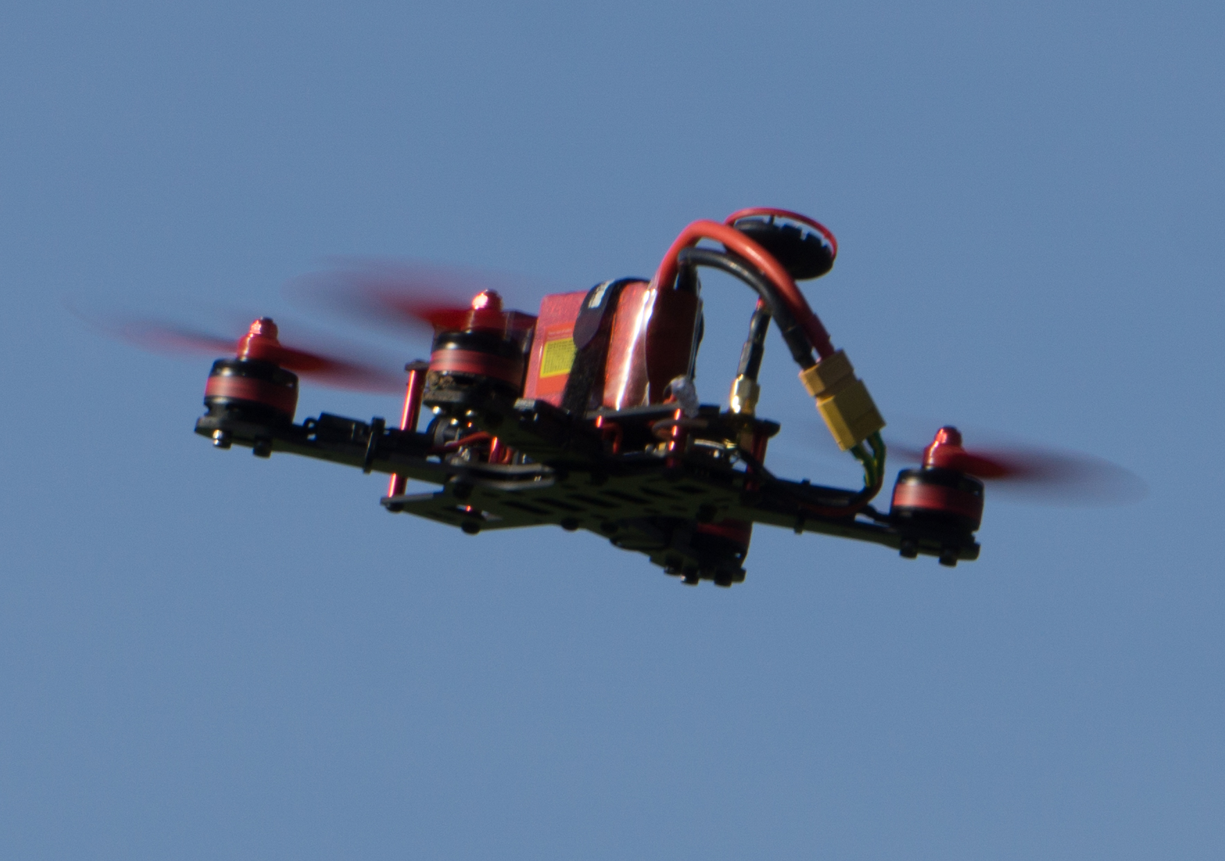
There are a few guides that show step-by-step how to assemble the copter. The most helpful is certainly the one from the Blog of Nathan Vertile.
However as a total newbie to the field of quad-copters and RC models We went through a bit of troubles to get everything working. So here are some notes that eventually got us to a flying model.
Note, that I will not cover the assembly of the copter in details as we did not have much trouble to follow the guides available on-line. I will mostly focus on the software and configuration part.
Besides the copter kit we used the following components:

  1. Radio Controler: FlySky FS-i6 with iA6B Receiver
  2. Eachine VR D2 Video Goggles
  3. LiPo Battery with an XT-60 Plug, 11.1V (3s), 1800mAh

To assemble the copter, follow the assembly instruction at:

  • RCGroups Forum: https://www.rcgroups.com/forums/showthread.php?t=2631690

The only thing note worthy is that the four motor controllers (ESCs) are not all connected the same. Pay attention to the direction the motors turn.
Connect the Receiver: Once the kit is assembled the receiver needs to be connected to the BRF3 flight controller.  We use FlySky IBUS port of the iA6B receiver and connect it to UART3 pin 1-3 (S.BUS) of the connector SB on the BRF3 board. IBUS is a FlySky proprietary interface using a UART channel to forward the control to the flight controller. It replaces the traditional PWM ports.
Flash Flight Controller with Firmware: 

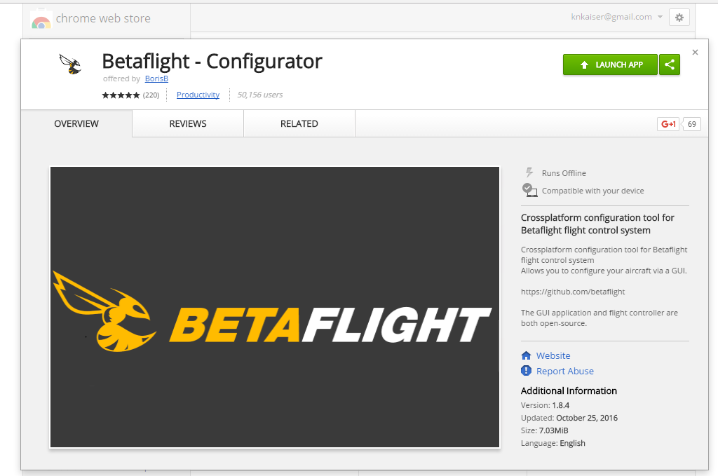
  1. In your Chrome browser click this link: Google Chrome App Store  and click the green “LAUNCH APP” button.
    Launch Betaflight
  2. Download the BetaFlight Firmware from here https://github.com/betaflight/betaflight/releases look out for the file: betaflight_x.x.x_SPRACINGF3.hex . I used Firmware Version 3.0.1.
  3. Click the “Load Firmware [Local]” button and load the betaflight_x.x.x_SPRACINGF3.hex file.
  4. Click “Flash Firmware”
    FW Update
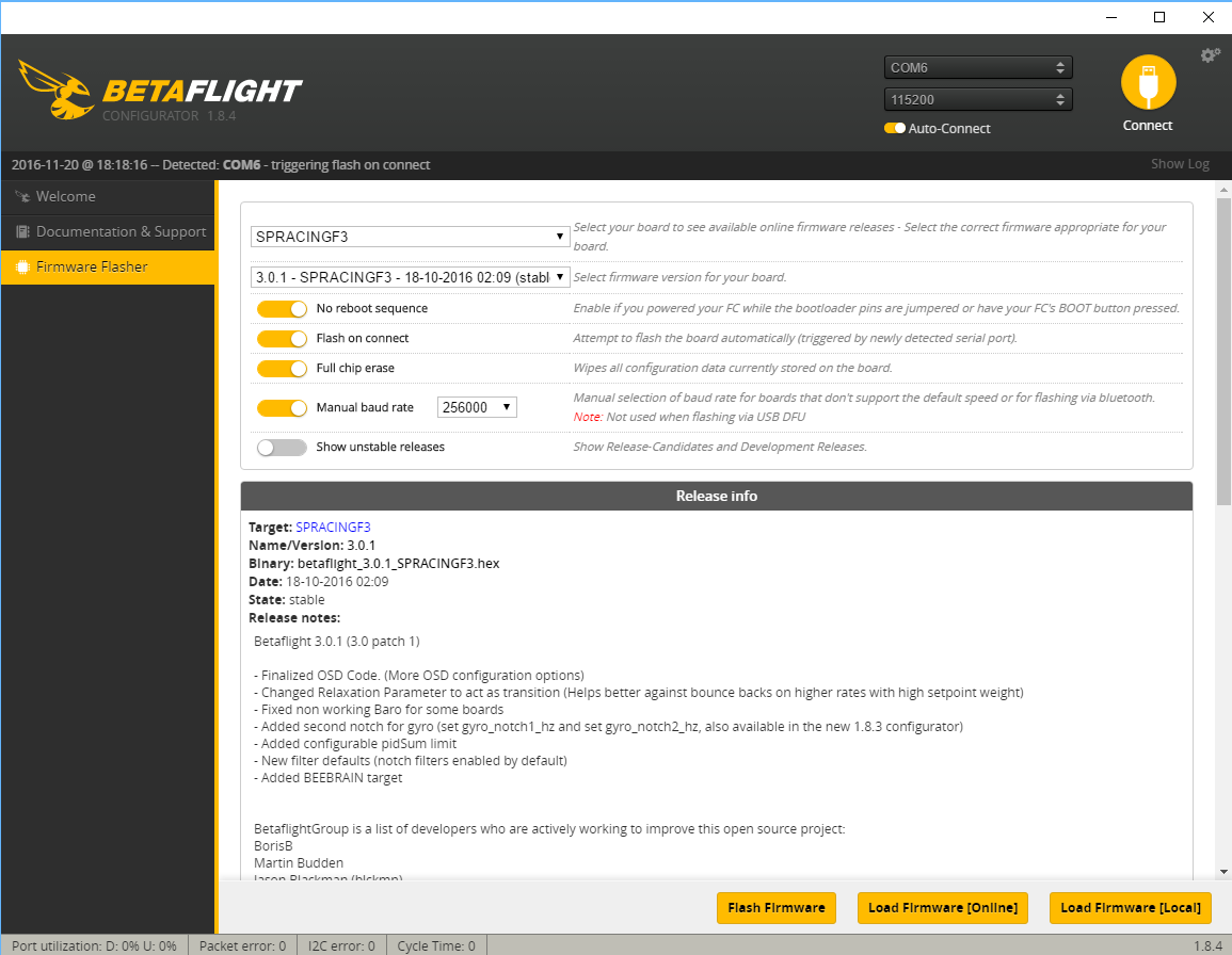
  5. Connect  your computer to the micro USB port of the BRF3 while holding the boot button next to the micro USB connector down. Do not connect the battery to the Victory230 the controller will get powered over the USB cable..
  6. The flash process should now start. Wait until completed successfully.

Note 1: you can also simply select “SPRACINGF3” in the firmware pull-down menu and click the “Load Firmware [Online]” button.
So now that we have flashed the correct firmware we do the same thing for the motor controllers (ESCs). The nice thing is we can use the BRF3 in pass-through to program the ESCs.
Update ESC Firmware: this is an optional step and I believe not really required. However because I did it I list the steps to perform it.

  1. Unconnect BRF3 from Betaflight
  2. Downolad BLHeli Suite
  3. Unzip it and open the program.
  4. Select Row “E SILABS BLHeli Bootloade (Cleanflight)”
    ESC FW Update
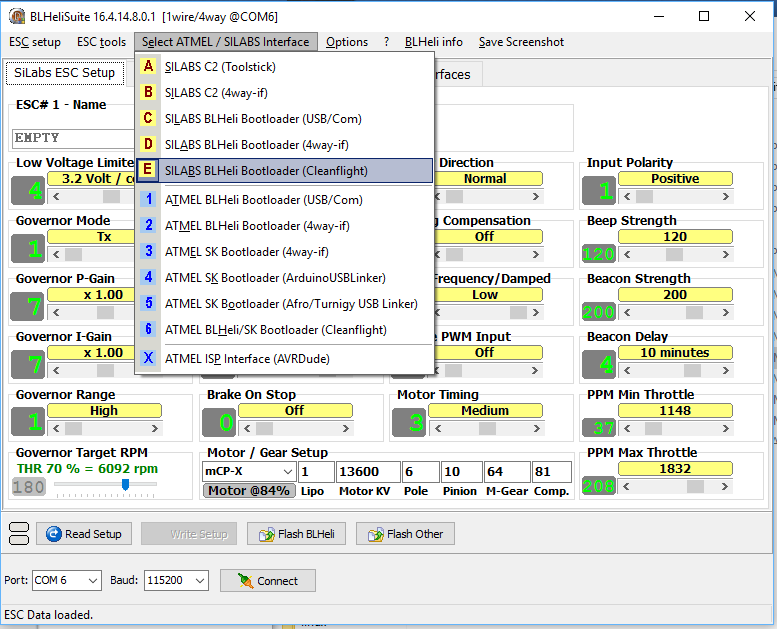
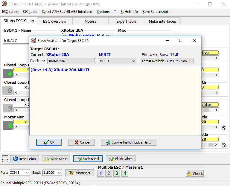
  5. Make sure the propellers are off and then click “Connect” button and then the “Check” button.
    ESC Check
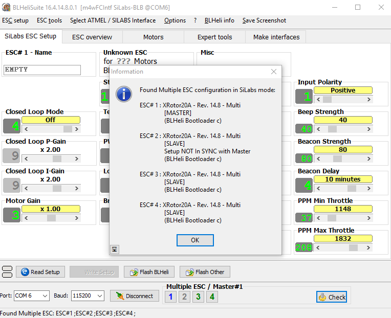
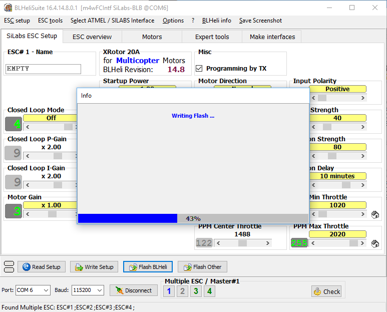
  6. Click “Flash BLHeli” and select “[Rev: 14.8] XRotor 20A MULTI” and then click OK
    ESC Select FW
  7. Wait until the flashing and verification is completed
    screenshot-2016-11-20-20-02-29
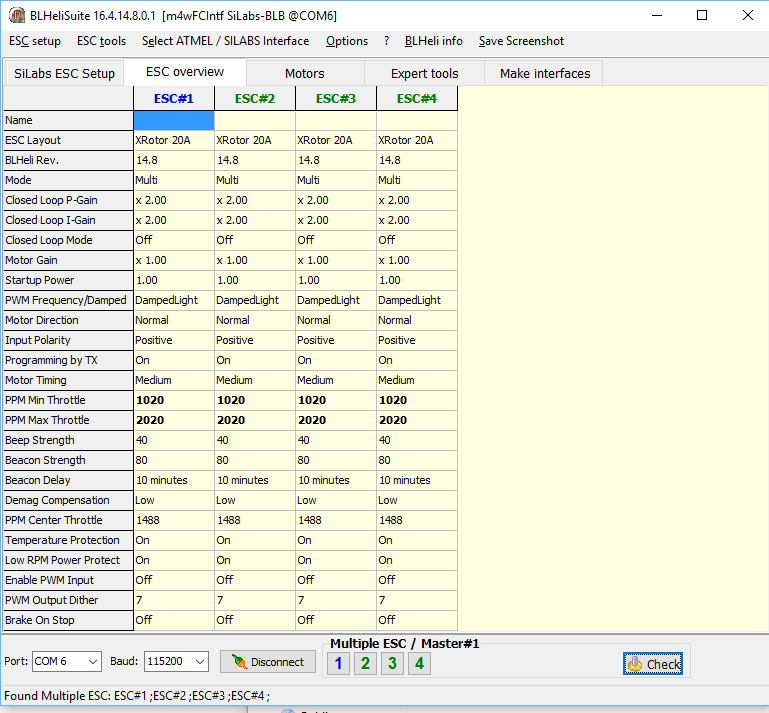
  8. Now you can check the setup of all four ESCs under the “ESC Overview” tab. Note the bold values are the only non-default settings.
    ESC Overview

Configure Flight Controller:

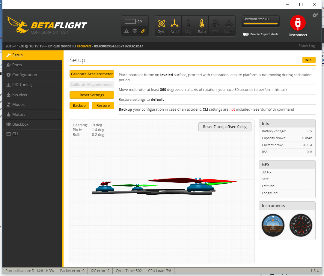
  1. Click the “Connect” button. Betaflight should now connect to your copter and the following screen will appear. If you have problems, check your COM port setting
  2. Put the Victory210 on a leveled surface and under the “Setup” tab click the “Calibrate Accelerometer” button. Then rotate it along all three axis at least 360 degrees within 30 seconds. Now the accelerometer should be properly calibrated.
    Calibration
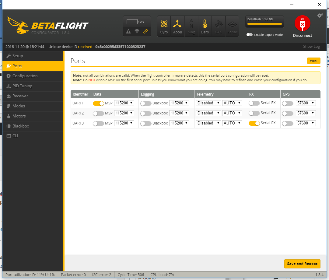
  3. Move to the “Ports” tab and select the “RX” of “UART3” to enable the connection between the BRF3 to the RC receiver.
    Ports
  4. Move to the “Configuration” tab and scroll down to “Battery Voltage” and set “Voltage Scale” to 210. Next turn under the “Current Sensor” the “CURRENT_METER” on. Set the “Scale the output voltage….” to 380. Now the under voltage and over current protection will go off at the right levels.
  5. Under “Receiver Mode” select “RX_SERIAL” to configure the BRF3 to understand the FlySky receiver connected to UART3
  6. Under “Serial Receiver Provider” select IBUS to the correct protocol for the FlySky receiver.
  7. Under “System Configuration” enable the “Barometer (if suppoted)” and click “Save and Reset”

Configure the FlySky Transmitter:

  1. There is not too much to configure. The transmitter should work out of the box and shipped already paired with the receiver.
  2. Although we use it for a copter make sure that it is configured to “Plane/Glider”

Calibrate Motors:

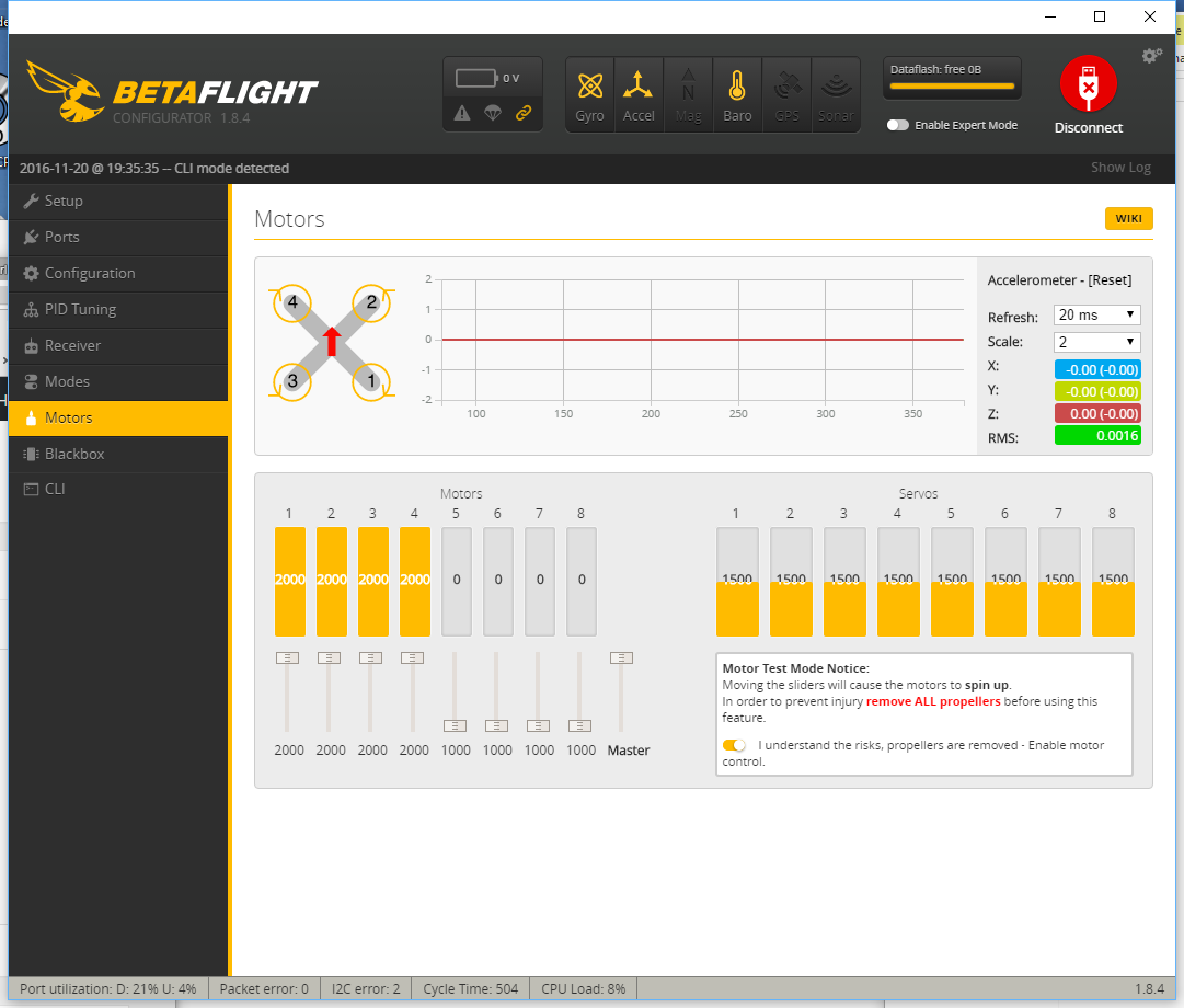
  1. Click on the “Motors” tab.
  2. Make sure your propellers are off! Then activate  “Enable motor control”
  3. Move the “Master” slider to 100%
    Motor Calibration
  4. Connect the battery and wait until the sound stops
  5. Move the “Master” slider to 0% and wait until the sound stops
  6. Unconnect the battery

Save configuration:

  1. Go to “CLI” Tab and enter “dump” into the command line
  2. Select the display output and cut and paste to a text editor and save the file.
  3. Here is the dump I got: BRF3 configuration

Note: once you have turned the “Expert Mode” on you can also save and restore configurations under the “Setup” tab.
Maiden Flight
Before we install the propellers we want to check a few things:

  • Check that when you move the sticks only the related chnannels are chaning. If that is not the case your Radio Controller may do some mixing so you want to check this.
  • Check the Motor control. The motors are secured until you push the throttle stick (in a normal setup the left stick on your RC) to the lower right corner. Once you do this a Beep will signal that the copter is armed and you should see all four motor bars to jump to 1070.

Now it is time to install the propellers and do a first flight test. Note the propellers are not all the same: pay attention to their shape before you mount them. Consider the motors turning directions and select the propeller that works for the related directions.

  1. Firmware: Even though Natan uses Clearflight I could not get it to work with their firmware

Resources and Credit:
A big Thank You goes to all the contributors of tools and software described in this post. I also want to acknowledge the blog posts from Nathan Vertile and the countless YouTube videos I used as guides for this post.

A DIY security video camera recorder (part 2) – beaglebone black host

2015-05-04 12.13.58In part 1 of this series I demonstrated how ffmpeg can be used to dump live video streams from IP cameras to a hard drive. In this post I will show how a Beaglebone Black board can be used to build a cheap and energy efficient video recorder.
Given that the recorder is not re-coding any of the camera streams the CPU requirements are quite moderate. The processor only collects the streaming data and copies them to a hard drive. Hence using a Mac or PC as a host platform is quite an over-kill. Also from an energy and cost point of view a smaller size computer is a much better fit. Embedded systems like the Rasberry Pi or Beaglebon Black should be perfectly capable of handling this task at a fraction of the cost.  So in the next few section I am going to walk you through the process of setting up such a IP-DVR system.

Hardware

Before we get into the details here is the hardware we will use:

  • Beagle Bone Black, 5 V power supply and >4 GB microSD card
  • Samsung IP camera
  • 3 Port USB Hub with Ethernet – I am using a “YUANXIN X-2104 Compact 3-Port USB 2.0 Hub w/ RJ45 Port + LED Indicator – Black + Grey”
  • 150GB – 1.5TGB USB 2.0 Harddisk
  • WiFi USB Dongle – 2.4 GHz 150Mbps Wireless IEEE802.11N Nano USB Adapter TP-LINK TL-WN725N

The Beaglebone Black (BBB) comes with a single USB 2.0 host and Ethernet port. For our setup we need at least 2 x Ethernet ports. One to connect the camera (LAN Port) and one for the connection to the internet (WAN port). The easiest way to add the second Ethernet port is the buy a USB-RJ45 Ethernet adapter. However this would occupy the USB 2.0 port so we also need a USB hub to add an additional port for the hard drive.
Fortunately there are combined 3-Port USB 2.0 Hub with RJ45 Port offered at your local computer store or on-line. They give you flexibility as you will have spare USB ports to add WIFI or other USB devices in the future.

Software

The following description assumes the latest BBB Debian Linux installation. If you are still using Angstrom please install the Debian Linux. No worries, it is very easy to do and there are many description out there that walk you through the steps. I just give an outline here assuming you use a Windows machine to write the Micro SD card.
Pull the lates image from the official site: http://beagleboard.org/latest-images. Then unpack the image with 7-Zip. You can now write the img-file with a utility like Win32DiskImager or WinFlashTool to your microSD card. Once the memory card is written you insert it into the BBB. Connect a USB hub with a keyboard and mouse and hook a Monitor to it. You are now ready to power the BBB up.
After a while the Linux environment should be visible on the screen.
If you use a SD card that offers more than 4GB of space like me you also want to increase the  BBB Image Disk Space. First make sure you boot from the mircoSD card, then adjust the Linux partition with fdisk.

fdisk /dev/mmcblk0p

execute the following single letter commands inside the fdisk utility:
1) Delete the second partition: d, 2
2) Create New Primary Linux Partition: n, p, 2
3) Write new partition table to disk: w
4) Exit fdisk: q
reboot and then adjust file system to use the extended partition:

resize2fs /dev/mmcblk0p2

reboot a second time so the change can take effect. You should now see the difference using the disk free utility:

df

Connect the BBB to the internet and update the package list:

sudo apt-get update

Before we start to install additional drivers we need to make sure the build tools and header files are installed:

sudo apt-get install build-essential
sudo apt-get install linux-headers-$(uname -r)

USB-Ethernet Driver

Now that we have an up-to-date Linux system we can start to install the drivers of the additional hardware. I will start with the USB-Ethernet interface first. My 3-Port USB 2.0 Hub with Ethernet Port uses the ASIX controller. To install the drivers follow the steps outlined below. Download the driver source from the ASIX’s web site, unpack the source code and compile it. Then install the driver:

make ~/ASIX
cd ~/ASIX
wget http://www.asix.com.tw/FrootAttach/driver/AX88772C_772B_772A_760_772_178_LINUX_DRIVER_v4.17.0_Source.tar.bz2
tar -xvf http://www.asix.com.tw/FrootAttach/driver/AX88772C_772B_772A_760_772_178_LINUX_DRIVER_v4.17.0_Source.tar.bz2
cd AX88772C_772B_772A_760_772_178_LINUX_DRIVER_v4.17.0_Source
make
sudo make install

Reboot and check in the /var/log/messages file to see if the module gets properly loaded:

grep asix /var/log/messages

and for a the Ethernet interface assigned to the port:

eth1: register 'asix' at usb-musb-hdrc.1.auto-1.1, ASIX AX88772C USB 2.0 Ethernet, .......

Now add the interface to your configuration file. In my case it is eth1:

sudo vi /etc/network/interfaces

the configuration file should look something like this:

# This file describes the network interfaces available on your system
# and how to activate them. For more information, see interfaces(5).
# The loopback network interface
auto lo
iface lo inet loopback
# The primary network interface
auto eth0
iface eth0 inet dhcp
# The secondary network interface
auto eth1
iface eth1 inet dhcp
......

Plug in an Ethernet cable connected to your network and activate the interface:

ifup eth1

The device should now fetch an IP address and once successful you are connected to the Internet.

The USB-WiFi Driver (optional, only required if you need support for WIFI)

The next driver we are going to install is for the USB TP-LINK TL-WN725N Wifi Dongle.
Important to know: there are TWO versions of the “TL-WN725N”, one needs the RTL8188CUS driver, the other needs this RTL8188EU. See wikidevi.com/wiki/TP-LINK_TL-WN725N_v1 and wikidevi.com/wiki/TP-LINK_TL-WN725N_v2 for differences.
These instructions are for the RTL8188EU version. Before you start confirm that your TP-LINK adapter is based on a RTL8188EU Realtek controller. Plug in the adapter and checkwith the following command:

lsusb

For my system I get the following response:

Bus 001 Device 002: ID 1a40:0101 Terminus Technology Inc. 4-Port HUB
Bus 001 Device 001: ID 1d6b:0002 Linux Foundation 2.0 root hub
Bus 002 Device 001: ID 1d6b:0002 Linux Foundation 2.0 root hub
Bus 001 Device 003: ID 0b95:772b ASIX Electronics Corp.
Bus 001 Device 006: ID 0bda:8179 Realtek Semiconductor Corp.

To install the Realtek driver follow the steps outlined below. Download the driver source from git, unpack the source code and compile it. Then install the driver:

mkdir ~/RTL8188EU
cd ~/RTL8188EU
git clone git://github.com/lwfinger/rtl8188eu
cd ~/RTL8188EU/rtl8188eu
make
sudo make install

Check that the driver is properly loaded:

sudo modprobe 8188eu

you  should be able to see the loaded driver with

lsmod

Check the interface and wireless signals

ifconfig
iwconfig

For me the system assigned the interface wlan2. I now edited the network interfaces file vi /etc/network/interfaces and add the wlan2

...
# WiFi Example
auto wlan2
iface wlan2 inet dhcp
    wpa-ssid "YOUR_SSID"
    wpa-psk "YOUR-PASSWORD"
......

The system is now configured such that we can bring up the wireless connection:

ifup wlan2

You can take down eth1 (ifdown eth1) before bring up (ifup) wlan2.

Webmin

I was looking for a tool similar to OpenWRT’s LUCI that allows me to administrate the BBB Debian Linux from a web browser. I settled on Webmin. Please leave  a comment if you have a better recommendation.
Webmin allows you to manage all to most common Linux services like retworks, firewalls, routing, sql, HTTP……. from simple web forms.
We are going to install Webmin via APT. The first step is to edit the /etc/apt/sources.list file on your system and add the lines :

deb http://download.webmin.com/download/repository sarge contrib
deb http://webmin.mirror.somersettechsolutions.co.uk/repository sarge contrib

Now APT can find the webmin repository. Run update to load the modified configuration:

apt-get update

Due to a known bug I had to change in the  /etc/apt/apt.conf.d/02compress-indexes file from  Acquire::GzipIndexes “true” to false:

...
Acquire::GzipIndexes "false";
...

Update the database and install webmin with the following commands:

sudo apt-get update
sudo apt-get install webmin

You can now point your browser to https://myhost:10000 and if everything is properly installed log into your system.
To connect the camera with a dynamic IP address we need to install the DHCP server:

sudo apt-get -y --force-yes -f install isc-dhcp-serve

Once the DHCP server is installed you need to add the things. The first is in the /etc/default/isc-dhcp-server file you need to add the following line:

INTERFACES="eth1"

So that the server will serve addressses on these two ports. The second thing you need is a DHCP configuration. It only needs correct sub-net definitions and point to the DNS servers of your choosing:

#
# Sample configuration file for ISC dhcpd for Debian
#
default-lease-time 600;
max-lease-time 7200;
authoritative;
# DNS server: Comcast and Google
option domain-name-servers 75.75.75.75, 75.75.75.76, 8.8.8.8;
# LAN SUbnet
subnet 10.10.11.0 netmask 255.255.255.0 {
option routers 10.10.11.1;
range 10.10.11.10 10.10.11.100;
}

I then used  firehol shell script to configure the firewall:

sudo apt-get update
sudo apt-get install firehol
vi /etc/default/firehol

You can let firebol guess your system and generate an example configuration

firehol helpme > /tmp/firehol.conf

Here is my /etc/firehol/firehol.conf

#
# Simple BBB firehol configuration file
#
version 5
interface eth1 mylan
    policy accept
interface eth0 mywan
    server http accept
    server ftp  accept
    server ssh  accept
    server webmin accept
    client all  accept
router mylan2mywan inface eth1 outface eth0
    masquerade
    route all accept

Now run firehol

sudo firehol start

If everything went well your firewall is now configured.

ffmpeg

It is now time to install ffmpeg tool.
You can again use APT to install ffmpeg. However this will get you a fairly dated version ffmpeg. Just add in your /etc/apt/sources.list

deb http://www.deb-multimedia.org wheezy main non-free
sudo apt-get update
sudo apt-get install ffmpeg

If you want the latest version follow the next few steps to compile from source code.

git clone git://source.ffmpeg.org/ffmpeg.git ffmpeg
cd ffmpeg
./configure --prefix=/usr/local
make
sudo make install

Now that all the tools are in place you can just follow the instruction of part 1 to capture and dump the video to the hard drive.

Conclusion

In this blog we learned to build a simple BBB based IP video recorder. With Debian Linux as the baseline I demonstrated how to install all the additional hardware drivers, tools and software such that the resulting server is able to record IP based video streams to a hard drive for a cost of less than $100 dollars.

Credits

To all the web sites, blog and forum posts I missed to record so that I could credit them here. To debian.org, elinux.org, webmin.com, ffmpeg.org, firehol.org and all the other contributing opensource communities that jointly created all the software used in this post.
 

Galileo is different, is it?

There a quite a number of Arduino boards available. The original Arduinos all used 8-bit AVR micro-controllers from Atmel. Recently Arduino adopted 32-bit ARM cores. In this post I want to look at the features of the Galileo board. The Board is about double the size of an original Arduino board and built around the Intel Quark X1000 controller.Galileo-circuitry_610x534 The Quark family of Intel chips are the new low cost line of x86 controllers that are positioned below the Atom cores.  Quarks are elementary particles that make up the atomic nucleus. Intel positions the Quark family for Internet of Things (IoT) applications. The X1000 controller is the first member of this line. The X1000 offers:

  • 400 MHz 32-bit x86 CPU
  • 512 Kbyte ECC protected embedded SRAM
  • Up to 2Gbyte external ECC protected DDR3 memory
  • 10 /100 Mbps Ethernet port with RMI interface
  • 2 x PCI Express Rev 2.0 ports offering up to 2.5 GT/s data transfer rates
  • 2 x USB 2.0 Host ports
  • 1 x USB 2.0 Device port
  • SDIO card interface
  • 2 x I2C Master interfaces up to 400 Kbit/s
  • 16 x GPIO
  • 2 x SPI Master controllers
  • 2 x 16550 compliant UART supporting baud rates from 300 to 2764800
  • Real Time Clock (RTC)

The controller is packed into a Flip-Chip Ball Grid Array (FCBGA) package with 393 solder balls that come with a 0.593 mm ball pitch. The package dimensions are 15mm x 15mm. With this kind of a package hand soldering is out of the picture.
Noteworthy is the implementation of the Arduino shield interface. The interface is pretty much designed with external components. For the GPIO/PWM digital shield pins a Cypress CY8C9540A 40-Bit I/O Expander with EEPROM  is used. The analog shield pins use an Analog Device AD7298 8-Channel, 1 MSPS, 12-Bit SAR Analog to Digital Converter (ADC) with Temperature Sensor . The Quark controller uses I2C serial interface to control the PGIO/PWM CY8C9540A device and the SPI for the ADC AD7298.

Galileo is coming to town

Today I received my Intel Galileo board that I ordered sometimes in October from Mouser.  The shipment date was initially mid November but got pushed back a few times. Anyway, I was planning to toy around with it over the holidays and was thrilled when it shipped December 24th. Galileo must have called Santa and put in a good word.
The board comes in a nice box together with a power supply. I wish it had stand-offs to provide some support when sitting on a table. This would prevent the board from resting on the mini-PCI card slot tips mounted on the back-side of the board. Those tips look like they could easily break off.
Anyway I will try to document the journey to get the board up and running.
For the documentation and software just head over to www.intel.com/support/go/galileo and download the related build for your OS. Intel supports 32/64 bit Linux, Windows and MacOS-X. The release as of this writing is 1.5.3 and gets delivered as a Zip-archive.
Downloading the Windows version and unzipping it with the stock Windows un-zipper produced an error because of too long file names in git related files. Using 7-Zip however completed without a hick-up (see also the Galileo Getting Started Guide) .
The next step is to plug in the power supply and connect the Client-USB port with a micro USB cable to your computer.  Once the Galileo USB port is detected by your computer (it shows up under “Gadget 2.4”) you must install the related serial drive. It can be found in the IDE installation directory under  ./hardware/arduino/x86/tools/linux-cdc-acm.inf .  Now it is time to start the arduino IDE and perform a firmware update. You can find the menu entry under Help->Firmware Update.

Olimexino-STM32

I have played around with the Arduino and had fun with it. However I am accustomed to more powerful micro-controllers than the AVR CPU. So it was only a matter of time until I started to look for an ARM based board that offered Arduino shields.  One board that caught my attention was the Olimexino-STM32 board.
OLIMEXINO-STM32-01
It is a nice board that offers the following key features:

  • STM32F103RB based ARM CPU
  • SD-Card slot
  • Mini USB port
  • CAN bus
  • Wide range of supply 9-30V
  • Battery supply plug

The board is a derivative of the Maple board from LeafLabs and also supports their Arduino like IDE.

Arduino Due

A few years back at Maker Fair in San Mateo, California I came across an Arduino Duemilanove board.
Arduino Duemilanove
I have been playing and earning a living with micro controllers for more than two decades. So naturally I was curious to learn more about what was at the heart of the Arduino movement. What better way than just try it out.
What  interested me was the ability to combine the Arduino board with shields. Therefore I also picked up a few shields, among them a LoL Shield.
Installing the Arduino IDE  was easy and with all the source code available on the internet I was quickly up and running, playing around with LEDs, servos and sensors.
This ease of use was probably the main reason why Arduino quickly became popular in DYI circles.