Author Archives: kkaiser

PMS5003 Sensor connected with I2C to ESPHome

Here is a simple example of how to use the Adafruit library https://github.com/adafruit/Adafruit_PM25AQI with a Custom Sensor in ESPHome.

# YAML File
esphome:
  name: bentoair
  platform: ESP32
  board: esp-wrover-kit
  includes:
    - BentoAir.h

  libraries:
    - "Adafruit PM25 AQI Sensor"
    - "Adafruit BusIO"
    - "SPI"
    
wifi:
  ssid: "..."
  password: "..."

  # Enable fallback hotspot (captive portal) in case wifi connection fails
  ap:
    ssid: "Air Quality Fallback Hotspot"
    password: "NSZIXXkPiruF"

captive_portal:

# Enable logging
logger:

# Enable Home Assistant API
api:

ota:

i2c:
  sda: 21
  scl: 22
  scan: True
  id: bus_a

sensor:
- platform: custom
  lambda: |-
    auto my_sensor = new MyCustomSensor();
    App.register_component(my_sensor);
    return {my_sensor->pm10s_sensor, my_sensor->pm25s_sensor, my_sensor->pm100s_sensor};

  sensors:
  - name: "PM1.0 Sensor"
    unit_of_measurement: ug/m3
  - name: "PM2.5 Sensor"
    unit_of_measurement: ug/m3
  - name: "PM10.0 Sensor"
    unit_of_measurement: ug/m3
 

And the C++ Custom Sensor file BentoAir.h looks like this:

#include "esphome.h"
#include "Adafruit_PM25AQI.h"

class MyCustomSensor : public PollingComponent, public Sensor {
 public:
 
  Adafruit_PM25AQI aqi = Adafruit_PM25AQI();

  Sensor *pm10s_sensor = new Sensor();
  Sensor *pm25s_sensor = new Sensor();  
  Sensor *pm100s_sensor = new Sensor();  
    
  MyCustomSensor() : PollingComponent(1000) { } // every 60 seconds

  void setup() override {
 
    delay(1000);
    if (! aqi.begin_I2C()) {      // connect to the sensor over I2C
      //if (! aqi.begin_UART(&Serial1)) { // connect to the sensor over hardware serial
      //if (! aqi.begin_UART(&pmSerial)) { // connect to the sensor over software serial 
      Serial.println("Could not find PM 2.5 sensor!");
      while (1) delay(10);
    }
  }

  void update() override {
    float temp_f;
    PM25_AQI_Data data;
    
    // Read AQI Sensor
    if (! aqi.read(&data)) {
      Serial.println("Could not read from AQI");
      delay(500);  // try again in a bit!
      return;
    }
    pm10s_sensor->publish_state(data.pm10_standard);
    pm25s_sensor->publish_state(data.pm25_standard);
    pm100s_sensor->publish_state(data.pm100_standard);
  }
};

Using a MeshBee with Smartthings

Since about six month I owned a Smartthings (ST) smart home hub from Samsung and have been pretty pleased with the functionality and openness of the platform. My home is equipped with wireless light switches that can be control from ST. So I started to add motion sensors to turn on and off lights in the basement and restrooms. My choice fell on the 2nd generation Iris Motion sensor from Loewe’s.  They are battery powered and so far have been reliable with the battery still at 76% after almost 6 months of service.
I quickly realized that the ST system was really flexible and open. Therefore it should not be too difficult to add custom-built sensors and actors to the ST hub. This post describes the first phase of trying to build my own wireless sensors and actors.
The ST hub hardware supports the following protocols to interact with sensors and actors. Among them TCP/IP (Ethernet, WiFi), Z-Wave, Zigbee, Bluetooth (not activated yet in ST hub).  As I wanted my sensors to be battery powered, WiFi solutions like the Particle Photon or ESP8266 fell by the wayside.  Therefore my focus turned to Z-Wave and Zigbee.
Z-Wave is a proprietary standard owned by Sigma Designs, Inc and uses different frequency bands in different geographic regions which leads to the available z-wave modules to be rather expensive. That said there is an interesting DIY board the Z-Uno but it is not yet available in the US Freq. Band and again fairly pricey.
Zigbee is the other candidate. This is an open standard that is supported by many semiconductor device manufacturers and there is a large selection of modules out there.
What I was looking for are solutions that allowed to write small programs to control or sense a few IO pins.  Many available modules use TI’s CC2x30 chips. These chips come with a built-in 8051 8 bit CPU. However, TI suggests using the IAR compiler and SDK. Unfortunately, it carries a price tag of ~$3000 which is hard to justify for a DIY project.  However, there is a Zigbee device that fits my needs pretty nicely and comes with a free SDK.  It is the JN5168 from Jennic that is now owned by NXP and soon by Qualcomm. I settled on a MeshBee (~$20) module from Seeedstudio together with a UartSBee V4 but I expect you can also use the SparkFun XBee Explorer Dongle or similar FTDI adapters.

Installing The JN5168 SDK and compiling the first Application

Head over to the NXP IEEE802.15.4 Page. You must register and login first before you can download the  BeyondStudio for NXP toolchain (JN-SW-4141). Then add the JN516x IEEE 802.15.4 SDK (JN-SW-4163)  to your installation by following the NXP installation instructions. I also installed the Flash Programmer (JN-SW-4107) .
Now that your SDK and toolchain are installed download the ZigBee Home Automation Demo  (JN-AN-1189) from the NXP web site. Unpack and import it into your Eclipse workspace as an “Existing Project into Workspace” under the tab “General”. Yshould now have something like this on your screen:

Go to “Project” -> “Build Configuration” -> “Set Active” and select item #9 “DimmableLight 1 (DR1175)”. Then select “Project” -> “Build All” or just use the command line:

make LIGHT=DimmableLight DR=DR1175 REV=r1v1 all

The compile takes quite long but once finished you should have a binary “DimmableLight_JN5168_DR1175_LED_EXP_MONO.bin”. Plug your Meshbee on top of the UartSbee. Make sure SW3 of the UartSBee is in the “Prog” position and connect UartSBee with a USB cable to your computer.   In Eclipse select from the “Device” -> “Program Device”. Program you MeshBee with the freshly compiled firmware.
You can now use your ST app on your phone to add a new device. After a while, the MeshBee should show up as a “Thing” device. Rename it to something of your choosing and save it.
Head over to your ST development environment, login and check under “My Devices”. You should see you freshly added device listed under the name you assigned. Click on the name and you will get a page like this:

Now click on the Edit button and change the “Type” to “Zigbee Dimmer” and save it by clicking the “Update” button

You should now get a proper Tile in your ST App on your phone. Click on the On/Off button and in the log you should see events being logged. Connect a LED or Voltmeter to D13 and you can see the LED turn on and off.
This blinky example is the “Hello World” demonstration of a Zigbee actor connected to a Smartthings hub.

Quadcopter BeeRotor Victory210

This is a bit of a leisurely post. After attending Maker Fair 2016 my son wanted to build a racing quad-copter. He did not want to buy a Ready To Fly (RTF) copter but rather a kit based on some recommendations from a pilot of the said show. Anyway, eventually we settled on the BeeRotor Victory210 from RCTimer.2016-11-24-14-27-47-editThere are a few guides that show step-by-step how to assemble the copter. The most helpful is certainly the one from the Blog of Nathan Vertile.
However as a total newbie to the field of quad-copters and RC models We went through a bit of troubles to get everything working. So here are some notes that eventually got us to a flying model.
Note, that I will not cover the assembly of the copter in details as we did not have much trouble to follow the guides available on-line. I will mostly focus on the software and configuration part.
Besides the copter kit we used the following components:

  1. Radio Controler: FlySky FS-i6 with iA6B Receiver
  2. Eachine VR D2 Video Goggles
  3. LiPo Battery with an XT-60 Plug, 11.1V (3s), 1800mAh

To assemble the copter, follow the assembly instruction at:

  • RCGroups Forum: https://www.rcgroups.com/forums/showthread.php?t=2631690

The only thing note worthy is that the four motor controllers (ESCs) are not all connected the same. Pay attention to the direction the motors turn.
Connect the Receiver: Once the kit is assembled the receiver needs to be connected to the BRF3 flight controller.  We use FlySky IBUS port of the iA6B receiver and connect it to UART3 pin 1-3 (S.BUS) of the connector SB on the BRF3 board. IBUS is a FlySky proprietary interface using a UART channel to forward the control to the flight controller. It replaces the traditional PWM ports.
Flash Flight Controller with Firmware: 

  1. In your Chrome browser click this link: Google Chrome App Store  and click the green “LAUNCH APP” button.
    Launch Betaflight
  2. Download the BetaFlight Firmware from here https://github.com/betaflight/betaflight/releases look out for the file: betaflight_x.x.x_SPRACINGF3.hex . I used Firmware Version 3.0.1.
  3. Click the “Load Firmware [Local]” button and load the betaflight_x.x.x_SPRACINGF3.hex file.
  4. Click “Flash Firmware”
    FW Update
  5. Connect  your computer to the micro USB port of the BRF3 while holding the boot button next to the micro USB connector down. Do not connect the battery to the Victory230 the controller will get powered over the USB cable..
  6. The flash process should now start. Wait until completed successfully.

Note 1: you can also simply select “SPRACINGF3” in the firmware pull-down menu and click the “Load Firmware [Online]” button.
So now that we have flashed the correct firmware we do the same thing for the motor controllers (ESCs). The nice thing is we can use the BRF3 in pass-through to program the ESCs.
Update ESC Firmware: this is an optional step and I believe not really required. However because I did it I list the steps to perform it.

  1. Unconnect BRF3 from Betaflight
  2. Downolad BLHeli Suite
  3. Unzip it and open the program.
  4. Select Row “E SILABS BLHeli Bootloade (Cleanflight)”
    ESC FW Update
  5. Make sure the propellers are off and then click “Connect” button and then the “Check” button.
    ESC Check
  6. Click “Flash BLHeli” and select “[Rev: 14.8] XRotor 20A MULTI” and then click OK
    ESC Select FW
  7. Wait until the flashing and verification is completed
    screenshot-2016-11-20-20-02-29
  8. Now you can check the setup of all four ESCs under the “ESC Overview” tab. Note the bold values are the only non-default settings.
    ESC Overview

Configure Flight Controller:

  1. Click the “Connect” button. Betaflight should now connect to your copter and the following screen will appear. If you have problems, check your COM port setting
  2. Put the Victory210 on a leveled surface and under the “Setup” tab click the “Calibrate Accelerometer” button. Then rotate it along all three axis at least 360 degrees within 30 seconds. Now the accelerometer should be properly calibrated.
    Calibration
  3. Move to the “Ports” tab and select the “RX” of “UART3” to enable the connection between the BRF3 to the RC receiver.
    Ports
  4. Move to the “Configuration” tab and scroll down to “Battery Voltage” and set “Voltage Scale” to 210. Next turn under the “Current Sensor” the “CURRENT_METER” on. Set the “Scale the output voltage….” to 380. Now the under voltage and over current protection will go off at the right levels.
  5. Under “Receiver Mode” select “RX_SERIAL” to configure the BRF3 to understand the FlySky receiver connected to UART3
  6. Under “Serial Receiver Provider” select IBUS to the correct protocol for the FlySky receiver.
  7. Under “System Configuration” enable the “Barometer (if suppoted)” and click “Save and Reset”

Configure the FlySky Transmitter:

  1. There is not too much to configure. The transmitter should work out of the box and shipped already paired with the receiver.
  2. Although we use it for a copter make sure that it is configured to “Plane/Glider”

Calibrate Motors:

  1. Click on the “Motors” tab.
  2. Make sure your propellers are off! Then activate  “Enable motor control”
  3. Move the “Master” slider to 100%
    Motor Calibration
  4. Connect the battery and wait until the sound stops
  5. Move the “Master” slider to 0% and wait until the sound stops
  6. Unconnect the battery

Save configuration:

  1. Go to “CLI” Tab and enter “dump” into the command line
  2. Select the display output and cut and paste to a text editor and save the file.
  3. Here is the dump I got: BRF3 configuration

Note: once you have turned the “Expert Mode” on you can also save and restore configurations under the “Setup” tab.
Maiden Flight
Before we install the propellers we want to check a few things:

  • Check that when you move the sticks only the related chnannels are chaning. If that is not the case your Radio Controller may do some mixing so you want to check this.
  • Check the Motor control. The motors are secured until you push the throttle stick (in a normal setup the left stick on your RC) to the lower right corner. Once you do this a Beep will signal that the copter is armed and you should see all four motor bars to jump to 1070.

Now it is time to install the propellers and do a first flight test. Note the propellers are not all the same: pay attention to their shape before you mount them. Consider the motors turning directions and select the propeller that works for the related directions.

  1. Firmware: Even though Natan uses Clearflight I could not get it to work with their firmware

Resources and Credit:
A big Thank You goes to all the contributors of tools and software described in this post. I also want to acknowledge the blog posts from Nathan Vertile and the countless YouTube videos I used as guides for this post.

A DIY security video camera recorder (part 2) – beaglebone black host

2015-05-04 12.13.58In part 1 of this series I demonstrated how ffmpeg can be used to dump live video streams from IP cameras to a hard drive. In this post I will show how a Beaglebone Black board can be used to build a cheap and energy efficient video recorder.
Given that the recorder is not re-coding any of the camera streams the CPU requirements are quite moderate. The processor only collects the streaming data and copies them to a hard drive. Hence using a Mac or PC as a host platform is quite an over-kill. Also from an energy and cost point of view a smaller size computer is a much better fit. Embedded systems like the Rasberry Pi or Beaglebon Black should be perfectly capable of handling this task at a fraction of the cost.  So in the next few section I am going to walk you through the process of setting up such a IP-DVR system.

Hardware

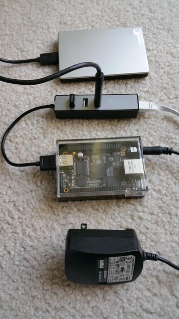
Before we get into the details here is the hardware we will use:

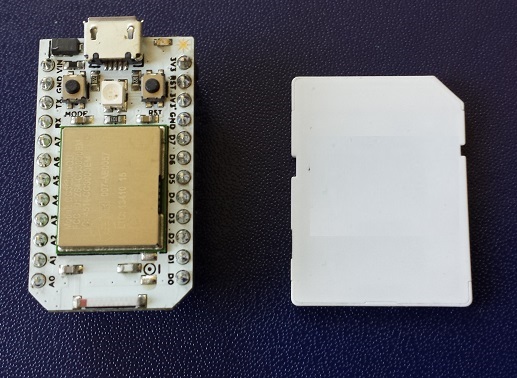
  • Beagle Bone Black, 5 V power supply and >4 GB microSD card
  • Samsung IP camera
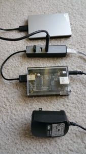
  • 3 Port USB Hub with Ethernet – I am using a “YUANXIN X-2104 Compact 3-Port USB 2.0 Hub w/ RJ45 Port + LED Indicator – Black + Grey”
  • 150GB – 1.5TGB USB 2.0 Harddisk
  • WiFi USB Dongle – 2.4 GHz 150Mbps Wireless IEEE802.11N Nano USB Adapter TP-LINK TL-WN725N

The Beaglebone Black (BBB) comes with a single USB 2.0 host and Ethernet port. For our setup we need at least 2 x Ethernet ports. One to connect the camera (LAN Port) and one for the connection to the internet (WAN port). The easiest way to add the second Ethernet port is the buy a USB-RJ45 Ethernet adapter. However this would occupy the USB 2.0 port so we also need a USB hub to add an additional port for the hard drive.
Fortunately there are combined 3-Port USB 2.0 Hub with RJ45 Port offered at your local computer store or on-line. They give you flexibility as you will have spare USB ports to add WIFI or other USB devices in the future.

Software

The following description assumes the latest BBB Debian Linux installation. If you are still using Angstrom please install the Debian Linux. No worries, it is very easy to do and there are many description out there that walk you through the steps. I just give an outline here assuming you use a Windows machine to write the Micro SD card.
Pull the lates image from the official site: http://beagleboard.org/latest-images. Then unpack the image with 7-Zip. You can now write the img-file with a utility like Win32DiskImager or WinFlashTool to your microSD card. Once the memory card is written you insert it into the BBB. Connect a USB hub with a keyboard and mouse and hook a Monitor to it. You are now ready to power the BBB up.
After a while the Linux environment should be visible on the screen.
If you use a SD card that offers more than 4GB of space like me you also want to increase the  BBB Image Disk Space. First make sure you boot from the mircoSD card, then adjust the Linux partition with fdisk.

fdisk /dev/mmcblk0p

execute the following single letter commands inside the fdisk utility:
1) Delete the second partition: d, 2
2) Create New Primary Linux Partition: n, p, 2
3) Write new partition table to disk: w
4) Exit fdisk: q
reboot and then adjust file system to use the extended partition:

resize2fs /dev/mmcblk0p2

reboot a second time so the change can take effect. You should now see the difference using the disk free utility:

df

Connect the BBB to the internet and update the package list:

sudo apt-get update

Before we start to install additional drivers we need to make sure the build tools and header files are installed:

sudo apt-get install build-essential
sudo apt-get install linux-headers-$(uname -r)

USB-Ethernet Driver

Now that we have an up-to-date Linux system we can start to install the drivers of the additional hardware. I will start with the USB-Ethernet interface first. My 3-Port USB 2.0 Hub with Ethernet Port uses the ASIX controller. To install the drivers follow the steps outlined below. Download the driver source from the ASIX’s web site, unpack the source code and compile it. Then install the driver:

make ~/ASIX
cd ~/ASIX
wget http://www.asix.com.tw/FrootAttach/driver/AX88772C_772B_772A_760_772_178_LINUX_DRIVER_v4.17.0_Source.tar.bz2
tar -xvf http://www.asix.com.tw/FrootAttach/driver/AX88772C_772B_772A_760_772_178_LINUX_DRIVER_v4.17.0_Source.tar.bz2
cd AX88772C_772B_772A_760_772_178_LINUX_DRIVER_v4.17.0_Source
make
sudo make install

Reboot and check in the /var/log/messages file to see if the module gets properly loaded:

grep asix /var/log/messages

and for a the Ethernet interface assigned to the port:

eth1: register 'asix' at usb-musb-hdrc.1.auto-1.1, ASIX AX88772C USB 2.0 Ethernet, .......

Now add the interface to your configuration file. In my case it is eth1:

sudo vi /etc/network/interfaces

the configuration file should look something like this:

# This file describes the network interfaces available on your system
# and how to activate them. For more information, see interfaces(5).
# The loopback network interface
auto lo
iface lo inet loopback
# The primary network interface
auto eth0
iface eth0 inet dhcp
# The secondary network interface
auto eth1
iface eth1 inet dhcp
......

Plug in an Ethernet cable connected to your network and activate the interface:

ifup eth1

The device should now fetch an IP address and once successful you are connected to the Internet.

The USB-WiFi Driver (optional, only required if you need support for WIFI)

The next driver we are going to install is for the USB TP-LINK TL-WN725N Wifi Dongle.
Important to know: there are TWO versions of the “TL-WN725N”, one needs the RTL8188CUS driver, the other needs this RTL8188EU. See wikidevi.com/wiki/TP-LINK_TL-WN725N_v1 and wikidevi.com/wiki/TP-LINK_TL-WN725N_v2 for differences.
These instructions are for the RTL8188EU version. Before you start confirm that your TP-LINK adapter is based on a RTL8188EU Realtek controller. Plug in the adapter and checkwith the following command:

lsusb

For my system I get the following response:

Bus 001 Device 002: ID 1a40:0101 Terminus Technology Inc. 4-Port HUB
Bus 001 Device 001: ID 1d6b:0002 Linux Foundation 2.0 root hub
Bus 002 Device 001: ID 1d6b:0002 Linux Foundation 2.0 root hub
Bus 001 Device 003: ID 0b95:772b ASIX Electronics Corp.
Bus 001 Device 006: ID 0bda:8179 Realtek Semiconductor Corp.

To install the Realtek driver follow the steps outlined below. Download the driver source from git, unpack the source code and compile it. Then install the driver:

mkdir ~/RTL8188EU
cd ~/RTL8188EU
git clone git://github.com/lwfinger/rtl8188eu
cd ~/RTL8188EU/rtl8188eu
make
sudo make install

Check that the driver is properly loaded:

sudo modprobe 8188eu

you  should be able to see the loaded driver with

lsmod

Check the interface and wireless signals

ifconfig
iwconfig

For me the system assigned the interface wlan2. I now edited the network interfaces file vi /etc/network/interfaces and add the wlan2

...
# WiFi Example
auto wlan2
iface wlan2 inet dhcp
    wpa-ssid "YOUR_SSID"
    wpa-psk "YOUR-PASSWORD"
......

The system is now configured such that we can bring up the wireless connection:

ifup wlan2

You can take down eth1 (ifdown eth1) before bring up (ifup) wlan2.

Webmin

I was looking for a tool similar to OpenWRT’s LUCI that allows me to administrate the BBB Debian Linux from a web browser. I settled on Webmin. Please leave  a comment if you have a better recommendation.
Webmin allows you to manage all to most common Linux services like retworks, firewalls, routing, sql, HTTP……. from simple web forms.
We are going to install Webmin via APT. The first step is to edit the /etc/apt/sources.list file on your system and add the lines :

deb http://download.webmin.com/download/repository sarge contrib
deb http://webmin.mirror.somersettechsolutions.co.uk/repository sarge contrib

Now APT can find the webmin repository. Run update to load the modified configuration:

apt-get update

Due to a known bug I had to change in the  /etc/apt/apt.conf.d/02compress-indexes file from  Acquire::GzipIndexes “true” to false:

...
Acquire::GzipIndexes "false";
...

Update the database and install webmin with the following commands:

sudo apt-get update
sudo apt-get install webmin

You can now point your browser to https://myhost:10000 and if everything is properly installed log into your system.
To connect the camera with a dynamic IP address we need to install the DHCP server:

sudo apt-get -y --force-yes -f install isc-dhcp-serve

Once the DHCP server is installed you need to add the things. The first is in the /etc/default/isc-dhcp-server file you need to add the following line:

INTERFACES="eth1"

So that the server will serve addressses on these two ports. The second thing you need is a DHCP configuration. It only needs correct sub-net definitions and point to the DNS servers of your choosing:

#
# Sample configuration file for ISC dhcpd for Debian
#
default-lease-time 600;
max-lease-time 7200;
authoritative;
# DNS server: Comcast and Google
option domain-name-servers 75.75.75.75, 75.75.75.76, 8.8.8.8;
# LAN SUbnet
subnet 10.10.11.0 netmask 255.255.255.0 {
option routers 10.10.11.1;
range 10.10.11.10 10.10.11.100;
}

I then used  firehol shell script to configure the firewall:

sudo apt-get update
sudo apt-get install firehol
vi /etc/default/firehol

You can let firebol guess your system and generate an example configuration

firehol helpme > /tmp/firehol.conf

Here is my /etc/firehol/firehol.conf

#
# Simple BBB firehol configuration file
#
version 5
interface eth1 mylan
    policy accept
interface eth0 mywan
    server http accept
    server ftp  accept
    server ssh  accept
    server webmin accept
    client all  accept
router mylan2mywan inface eth1 outface eth0
    masquerade
    route all accept

Now run firehol

sudo firehol start

If everything went well your firewall is now configured.

ffmpeg

It is now time to install ffmpeg tool.
You can again use APT to install ffmpeg. However this will get you a fairly dated version ffmpeg. Just add in your /etc/apt/sources.list

deb http://www.deb-multimedia.org wheezy main non-free
sudo apt-get update
sudo apt-get install ffmpeg

If you want the latest version follow the next few steps to compile from source code.

git clone git://source.ffmpeg.org/ffmpeg.git ffmpeg
cd ffmpeg
./configure --prefix=/usr/local
make
sudo make install

Now that all the tools are in place you can just follow the instruction of part 1 to capture and dump the video to the hard drive.

Conclusion

In this blog we learned to build a simple BBB based IP video recorder. With Debian Linux as the baseline I demonstrated how to install all the additional hardware drivers, tools and software such that the resulting server is able to record IP based video streams to a hard drive for a cost of less than $100 dollars.

Credits

To all the web sites, blog and forum posts I missed to record so that I could credit them here. To debian.org, elinux.org, webmin.com, ffmpeg.org, firehol.org and all the other contributing opensource communities that jointly created all the software used in this post.
 

A DIY security video camera recorder (part 1) – the missing newspaper

2015-04-28 10.56.31-3Over the last few month 1-2 a week our newspaper was missing. This, most of the mornings, really ticket me off as it disrupted my breakfast routine. A while later I got a letter from the courier announcing that in our neighborhood newspapers get stolen.
I need my morning newspaper even though there is hardly any news in there. I considered cancelling the subscription but realized that I was not ready to let go of this habit. I also grew curious who would steal newspapers when most of the news was freely available on-line. Maybe one of my lovely neighbors had a dark side. So I took the challenge and set out to solve this mystery.
I ordered a Samsung SNH-P6410BN in-door and Samsung SNH-E6440BN outdoor wireless IP security camera. These are really great Hi-Def cameras with a wide field of view and good picture quality during daylight as well as at night.
The camera comes with pretty decent cloud support and an Android and iPhone app. It can store the video feeds to microSD cards that can be inserted into the cameras.  However I did not want to fiddle with SD-cards as the camera is connected to my network and I hoped that additional software could help me out.
I was intrigued by 3rd party Video Software like BlueIris that could in fact connect to my cameras video streams.
While setting up my camera with BlueIris I realized that the camera is able to stream video in any of the following resolutions:

Video Profile 6: h264 (Baseline), yuv420p, 640x360, 30 tbr, 90k tbn, 180k tbc
Video Profile 5: h264 (Baseline), yuv420p, 1920x1080, 30 tbr, 90k tbn, 180k tbc
Video Profile 4: h264, yuv420p, 1280x720, q=2-31, 90k tbn, 90k tbc:
Video Profile 3: h264 (Baseline), yuv420p, 640x360, 30 tbr, 90k tbn, 180k tbc
Video Profile 2: h264 (Baseline), yuv420p, 640x360, 10 fps, 10 tbr, 90k tbn, 180k tbc
Video Profile 1: mjpeg, yuvj420p(pc, bt470bg/unknown/unknown), 1920x1080 [SAR 1:1 DAR 16:9], 1 tbr, 90k tbn, 90k tbc

This is no where documented in the product manual that shipped with the camera.  Anyway, I managed to open the camera streams in VLC and watch the live feed using a URL like this:

rtsp://admin:YOUR_PASSWORD@192.168.1.100/profile5/media.smp

However I was mostly interested in dumping these streams to a hard drive so that I could zap through them with VLC. That is when I started to look into ffmpeg.
What a tool this is! The Swiss-Army knife of Video. Is there something that cannot be done with this utility? However, the flexibility comes at a price. There are so many options and parameters that exploring them feels like an entry riddle to a secret society. That said, the ffmpeg user community is large and there are many example and posts that are available on the internet to get you started.
So here is a simple command that dumps my stream:

ffmpeg -i rtsp://admin:YOUR_PASSWORD@192.168.1.100/profile5/media.smp -vcodec copy VideoDump.mp4

This line dumps the input video stream into the file VideoDump.mp4. The option “-vcodec copy” makes sure that the stream is not re-coded so the process hardly takes any CPU resources. This worked really well. However the files started to become big as a 1920×1080 stream uses about 1 GByte of hard disk space per hour. Is there a way to split the files into 1hour segments? You bet!
The following command line will dump segments of 1 hour:

ffmpeg -i rtsp://admin:YOUR_PASSWORD@192.168.1.100/profile5/media.smp -vcodec copy -segment_time 3600 -segment_time_delta 0.03 -reset_timestamps 1 VideoDump_%03d.mp4

The segment time is specified with the option “-segment_time 3600” that takes seconds as the argument. The option “-segment_time_delta 0.03″ allows the utility some 0.03 second flexibiliy where to cut a segment so it can do it at a key frame. The option ” -reset_timestamps 1″ will reset the time inside a segment to start at 00:00. Also the segments get numbered. The segment files are named like this:

VideoDump_000.mp4
VideoDump_001.mp4
VideoDump_002.mp4
 :
 :

The amount of video data I collected was rapidly growing and I was interested to start and turn off the capturing at define moments. Sure ffmpeg can do this:

ffmpeg -i rtsp://admin:YOUR_PASSWORD@192.168.1.100/profile5/media.smp -vcodec copy -segment_time 3600 -segment_time_delta 0.03 -reset_timestamps 1 -ss 00:00:00 -t 02:30:00 VideoDump_%03d.mp4

Adding the option “-ss 00:00:00 -t 02:30:00” will capture 2.5 hours of footage and then stop. I then used a cron job on my Mac to start the stream capturing.

In summary ffmpeg works great with the Samsung IP cameras and allows to capture videos exactly during the hours of interest.

So coming back to the missing newspaper, you wonder who the culprit was? Well to my surprise there was no thief. The footage clearly revealed that the newspaper never got delivered the days it was “stolen”.

Logging Weather Data to the Cloud

In this post I want to report some of the finding from a 4 month experiment with a Spark Core. The core is uploading pressure measurement values into the cloud every five minutes. It then loggs them into a Google Spreadsheet. I use the Spark Temboo library and service after I failed to reliably poll the core from Google.
Anyway the Spreadsheet has now more than 30,000 entries. The chart generation is a bit slow but everything is still running stable to this day. A plot of the 4 month is shown below:
Temboo
After a measurement is taken the core goes to deep sleep to conserve energy. An STM103 internal HW timer interrupt is used to wake-up in time for the next measurement.
Over the four month I have seen only a few corrupted values. These are most likely transmission errors due to network connectivity issues.

PCB Design Workshop

Last weekend I attended a cool 1 day workshop “Designing a Circuit Board” given by Matt Berggren. Matt is a member of supplyframe San Francisco with many years of experience as a PCB designer and instructor.
The class is positioned as “Learn to Build a PCB from the ground up…” targeting hackers and professionals that want to tip their toes into the water of hardware design. This was the 4th installment of this class that always fills up withing a very short time.
Matt is an engaging presenter. He spent the morning explaining the fundamentals of PCB boards and technology. The class does’t assuming an EE degree so Matt is careful to explain the fundamentals and terms relevant for PCB design. In fact he is quite a master in catering to the beginners and more advanced members of his audience.
Here is an overview of the topics Matt covered in the morning:

  • Circuit Board basics and terminology – layers, cores, finishes, objects (pads, vias, components, lands, land patterns, footprints, vias), multilayer vs. single-layer, layer types, etc.
  • Some electrical basics related to boards – dielectrics, copper considerations, current carrying, impedance control, parasitic capacitance (don’t freak out, we’ll explain all of this)

The afternoon was mostly spent hands-on working with Eagle. Here is what we covered:

  • Build our first schematic + PCB + CAM (simple USB power supply that generates some very basic voltages we can use on the bench to do stuff – very simple USB->LDO->Connector)
  • Looked at Eagle and learn some important Eagle terminology, basics of the menus, command line interface, shortcuts, etc + basic workflow (should prepare you for doing this on your own)

Cudo and thanks to Matt. He runs these classes for free at weekends. His audience’s backgrounds are very divers. Some are complete electronic novices and some are pros. Matt masters this challenge by providing a lot of well selected practical technical information with entertaining anecdotes. Great teaching job.

Updated Temboo library available

I finally found some time to fix the problems with the Spark Temboo library. The following issues were fixed:

  • mib(), max() definition clash between the STL library and the Spark Wiring math library.
  • Misc makefile fixes to build the library from a shell

The updated source code is available at Github under https://github.com/bentuino/temboo.git Thanks to all the notes and hits I received from the community.

Temboo ignited with a Spark

This is a re-post of an article I wrote as a guest blogger for Temboo’s blog.
I am working with connected devices and was looking for a cloud service. While surveying the field Temboo caught my eye because of the large number of supported premium web sites and the promise to connect IoT devices to the Internet in a breeze.
spark_size The connected device I am using is a Spark Core. The Spark Core is a sleek small board that offers a powerful 32 bit ARM CPU paired with WiFi. The product grew out of a Kickstarter campaign and is rapidly gaining in popularity. The Spark is nicely priced and everything is open source. The team supporting the Spark Core is smart and supportive and made a great choice to port most of the main Arduino APIs to their platform.
As outline in a blog post here migrating Arduino Libraries to the Spark Core often turns out to be pretty easy. With Temboo providing an open source library for Arduino I was tempted to give it a try. However, I had no Temboo-Arduino setup so I was not sure how hard it would be to get it all up and running.
Well, I am happy to report that is was easier than expected. Temboo’s code is well written. I only had to work around some AVR specific optimizations that Temboo did to save program memory. As the Spark Core is built around a STM32F103 chip resources are not as tight as with the AVR so I simply bypassed these optimizations.
Here are some brief instructions how to install the Temboo Arduino Library. The instructions use the Spark command line SDK setup:

  1. Download the modified Temboo Arduino Library source code from github:
    mkdir temboo
    cd temboo
    git clone https://github.com/bentuino/temboo.git
  2. Get the Spark Core firmware:
    git clone https://github.com/spark/core-firmware.git
    git clone https://github.com/spark/core-common-lib.git
    git clone https://github.com/spark/core-communication-lib.git
    // Merge the two source codes
    cp -fr core-* temboo
    rm -fr core-*
  3. In older Spark firmware there is a small problem that the spark team already fixed. Open the file core-firmware/inc/spark_wiring_ipaddress.h and uncomment the line 54 with your favorite editor:
    // Overloaded cast operator to allow IPAddress objects to be used where a pointer
    // to a four-byte uint8_t array is expected
    //operator uint32_t() { return *((uint32_t*)_address); };
    bool operator==(const IPAddress& addr) { return (*((uint32_t*)_address)) == (*((uint32_t*)addr._address)); };
    bool operator==(const uint8_t* addr);
  4. Save your TembooAccount.h you generated with DeviceCoder to temboo-arduino-library-1.2\Temboo
  5. Now it is time to build the Spark application:
    cd temboo/core-firmware/build
    make -f makefile.temboo clean all
  6. Connect your Spark Core to your computer via a USB cable
  7. Push both buttons, release Reset button and continue holding the other button until RGB-LED lights up yellow
  8. Download application into Spark Core
    make -f makefile.temboo program-dfu

Temboo Examples

Two simple Spark application examples are included:

  • core-firmware/src/application_gxls.cpp – Example demonstrates the Temboo library with Google Spreadsheet
  • core-firmware/src/application_gmail.cpp – Example demonstrates the Temboo library with Gmail

to change the example that is built, edit the first line in the core-firmware/src/build.mk file:

CPPSRC += $(TARGET_SRC_PATH)/application_gxls.cpp

or

CPPSRC += $(TARGET_SRC_PATH)/application_gmail.cpp

Building this code was tested under Windows 8.1 using cygwin and the MINGW version of the ARM GCC compiler tool chain. It should be easy to use this Temboo Library with the Spark Cloud based SDK. To configure the Library to support Spark all the is required is to define the following label:

CFLAGS += -DSPARK_PRODUCT_ID=$(SPARK_PRODUCT_ID)

or add a

#define SPARK_PRODUCT_ID SPARK_PRODUCT_ID

to the source code. Temboo support for the Spark Core is a lot of fun. It is easy to setup your own Temboo account and compile the Temboo Arduino Library that now supports the Spark Core platform. To learn more about similar projects please visit my blog at http://bentuino.com.