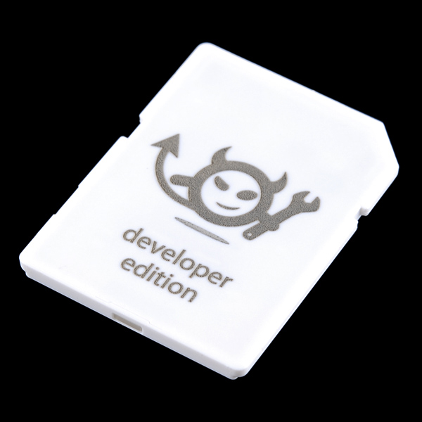
At the CES 2014 Intel announced the Edison platform that is intended to enable IoT applications. As pointed out in my earlier blog, there is a pretty similar solution out there. It goes by the name of Electric Imp.


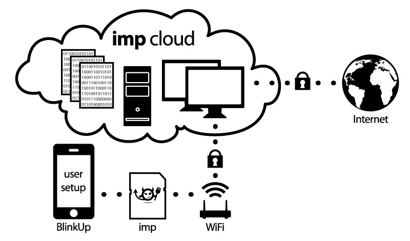
The Electric Imp is a platform that consist of several parts:
- The SD-Card size Electric Imp
- A web based IDE
- A cloud service that integrates with the Electric Imp hardware
- The BlinkUp cell phone app to pair the Imp Hardware with your local network and Electric Imp web services
Such an impressive combination promised some fun, so I was curious how well all the components would work together. To try it out I got myself an Electric Imp and the related Imp Arduino Shield from Sparkun. In order to use it with Arduino Shields or Arduino Boards you have to also order the headers and solder them on the board. I use the Arduino Stackable Header Kit . The stackable header allow you to use the Imp as a “WiFi Shield” to an Arduino Single Board Computer (SBC) as well as being a standalone SBC. If you only use you Electric Imp as a SBC you won’t need any stackable headers. Also make sure you order the headers that fits your Arduino board. There are different revisions out there. The R3 version has additional pins and will not fit an original Arduino board.
Once the headers are soldered down you can plug the Electric Imp Shield on top of an Arduino board. Signup for an account on http://electricimp.com and download the BlinkUp app to your smartphone. Fire-up the app and log into your Electric Imp account with your credentials. It’s time to power up the Arduino-Imp combo. Hold your Phone screen flush with the front edge of the Electric Imp card and start the pairing process. The phone screen flashes for a while. Once the flashing stops the Electric Imps status light should turn green. You can get detail instructions on the Electric Imp web site or on Sparkfun. So far not a lot of challenges.
Time has come to whip together some code that brings this combo to life. To test the Electric Imp I used some modify code from their web site.
// create a global variabled called led,
// and assign pin9 to it
led8 <- hardware.pin8;
led9 <- hardware.pin9;
// configure led to be a digital output
led8.configure(DIGITAL_OUT);
led9.configure(DIGITAL_OUT);
// create a global variable to store current
// state of the LED
state <- 0;
function blink() {
  // invert the value of state:
  // when state = 1, 1-1 = 0
  // when state = 0, 1-0 = 1
  state = 1-state;
  // write current state to led pin #8
  led8.write(state);
  // schedule imp to sleep for .5 seconds.
  imp.sleep(0.5);
  // write current state to led pin #9
  led9.write(state);
  // schedule imp to wakeup in .5 seconds and do it again.
  imp.wakeup(0.5, blink);
}
// start the loop
blink();
The code above let’s the two LEDs on the Electric Imp Shield blink alternatively for half a second each. So if you see the LEDs blinking, you know that the IDE properly compiled it and downloaded it over the internet into the Electric Imp card where it gets properly executed. Well Done! Stay tuned, in my next installment I will try to get the Electric Imp talk to the Arduino.