Since about six month I owned a Smartthings (ST) smart home hub from Samsung and have been pretty pleased with the functionality and openness of the platform. My home is equipped with wireless light switches that can be control from ST. So I started to add motion sensors to turn on and off lights in the basement and restrooms. My choice fell on the 2nd generation Iris Motion sensor from Loewe’s. They are battery powered and so far have been reliable with the battery still at 76% after almost 6 months of service.
I quickly realized that the ST system was really flexible and open. Therefore it should not be too difficult to add custom-built sensors and actors to the ST hub. This post describes the first phase of trying to build my own wireless sensors and actors.
The ST hub hardware supports the following protocols to interact with sensors and actors. Among them TCP/IP (Ethernet, WiFi), Z-Wave, Zigbee, Bluetooth (not activated yet in ST hub). As I wanted my sensors to be battery powered, WiFi solutions like the Particle Photon or ESP8266 fell by the wayside. Therefore my focus turned to Z-Wave and Zigbee.
Z-Wave is a proprietary standard owned by Sigma Designs, Inc and uses different frequency bands in different geographic regions which leads to the available z-wave modules to be rather expensive. That said there is an interesting DIY board the Z-Uno but it is not yet available in the US Freq. Band and again fairly pricey.
Zigbee is the other candidate. This is an open standard that is supported by many semiconductor device manufacturers and there is a large selection of modules out there.
What I was looking for are solutions that allowed to write small programs to control or sense a few IO pins. Many available modules use TI’s CC2x30 chips. These chips come with a built-in 8051 8 bit CPU. However, TI suggests using the IAR compiler and SDK. Unfortunately, it carries a price tag of ~$3000 which is hard to justify for a DIY project. However, there is a Zigbee device that fits my needs pretty nicely and comes with a free SDK. It is the JN5168 from Jennic that is now owned by NXP and soon by Qualcomm. I settled on a MeshBee (~$20) module from Seeedstudio together with a UartSBee V4 but I expect you can also use the SparkFun XBee Explorer Dongle or similar FTDI adapters.
Installing The JN5168 SDK and compiling the first Application
Head over to the NXP IEEE802.15.4 Page. You must register and login first before you can download the BeyondStudio for NXP toolchain (JN-SW-4141). Then add the JN516x IEEE 802.15.4 SDK (JN-SW-4163) to your installation by following the NXP installation instructions. I also installed the Flash Programmer (JN-SW-4107) .
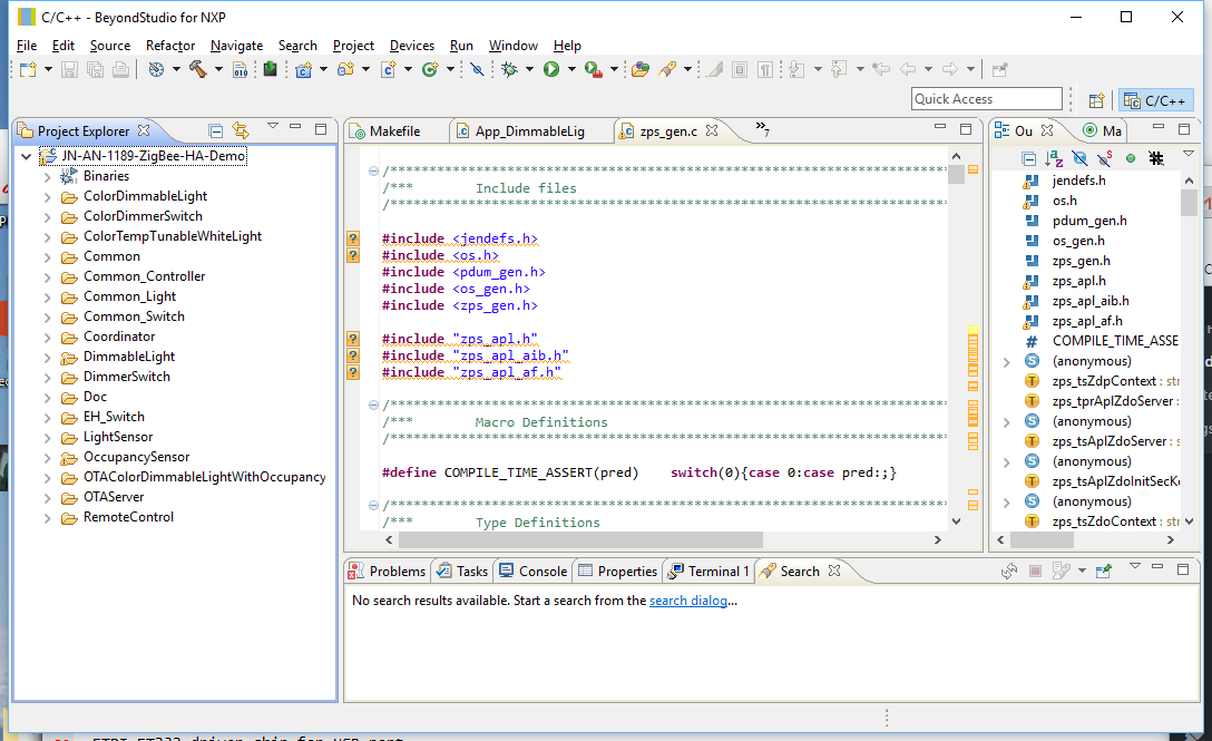
Now that your SDK and toolchain are installed download the ZigBee Home Automation Demo (JN-AN-1189) from the NXP web site. Unpack and import it into your Eclipse workspace as an “Existing Project into Workspace” under the tab “General”. Yshould now have something like this on your screen:

Go to “Project” -> “Build Configuration” -> “Set Active” and select item #9 “DimmableLight 1 (DR1175)”. Then select “Project” -> “Build All” or just use the command line:
make LIGHT=DimmableLight DR=DR1175 REV=r1v1 all
The compile takes quite long but once finished you should have a binary “DimmableLight_JN5168_DR1175_LED_EXP_MONO.bin”. Plug your Meshbee on top of the UartSbee. Make sure SW3 of the UartSBee is in the “Prog” position and connect UartSBee with a USB cable to your computer. In Eclipse select from the “Device” -> “Program Device”. Program you MeshBee with the freshly compiled firmware.
You can now use your ST app on your phone to add a new device. After a while, the MeshBee should show up as a “Thing” device. Rename it to something of your choosing and save it.
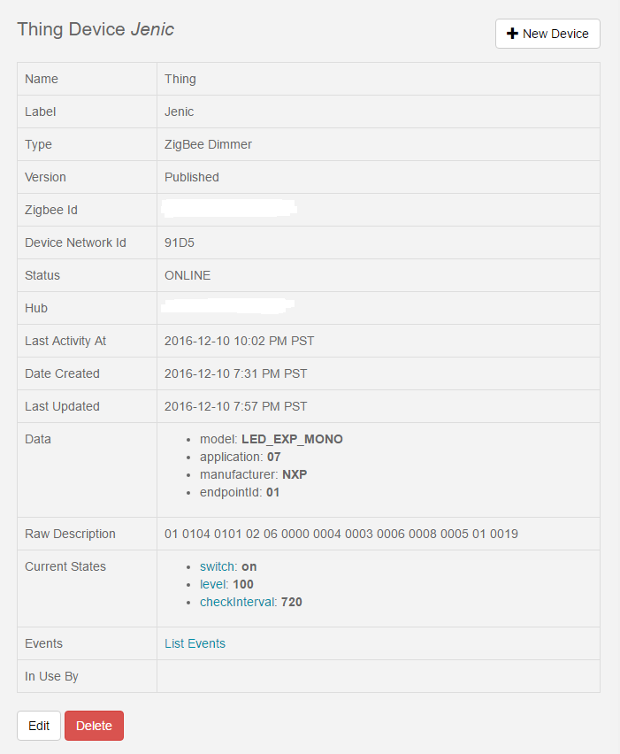
Head over to your ST development environment, login and check under “My Devices”. You should see you freshly added device listed under the name you assigned. Click on the name and you will get a page like this:

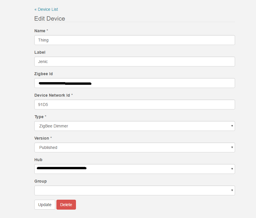
Now click on the Edit button and change the “Type” to “Zigbee Dimmer” and save it by clicking the “Update” button

You should now get a proper Tile in your ST App on your phone. Click on the On/Off button and in the log you should see events being logged. Connect a LED or Voltmeter to D13 and you can see the LED turn on and off.
This blinky example is the “Hello World” demonstration of a Zigbee actor connected to a Smartthings hub.