IoT

Using a MeshBee with Smartthings

Since about six month I owned a Smartthings (ST) smart home hub from Samsung and have been pretty pleased with the functionality and openness of the platform. My home is equipped with wireless light switches that can be control from ST. So I started to add motion sensors to turn on and off lights in the basement and restrooms. My choice fell on the 2nd generation Iris Motion sensor from Loewe’s.  They are battery powered and so far have been reliable with the battery still at 76% after almost 6 months of service.
I quickly realized that the ST system was really flexible and open. Therefore it should not be too difficult to add custom-built sensors and actors to the ST hub. This post describes the first phase of trying to build my own wireless sensors and actors.
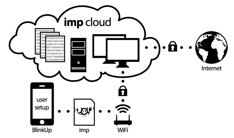
The ST hub hardware supports the following protocols to interact with sensors and actors. Among them TCP/IP (Ethernet, WiFi), Z-Wave, Zigbee, Bluetooth (not activated yet in ST hub).  As I wanted my sensors to be battery powered, WiFi solutions like the Particle Photon or ESP8266 fell by the wayside.  Therefore my focus turned to Z-Wave and Zigbee.
Z-Wave is a proprietary standard owned by Sigma Designs, Inc and uses different frequency bands in different geographic regions which leads to the available z-wave modules to be rather expensive. That said there is an interesting DIY board the Z-Uno but it is not yet available in the US Freq. Band and again fairly pricey.
Zigbee is the other candidate. This is an open standard that is supported by many semiconductor device manufacturers and there is a large selection of modules out there.
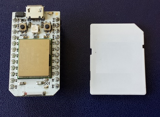
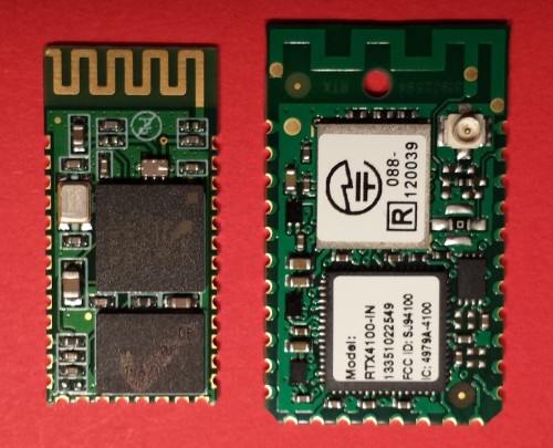
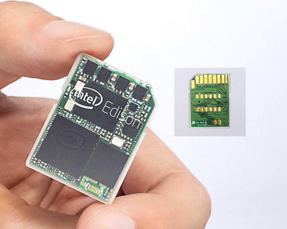
What I was looking for are solutions that allowed to write small programs to control or sense a few IO pins.  Many available modules use TI’s CC2x30 chips. These chips come with a built-in 8051 8 bit CPU. However, TI suggests using the IAR compiler and SDK. Unfortunately, it carries a price tag of ~$3000 which is hard to justify for a DIY project.  However, there is a Zigbee device that fits my needs pretty nicely and comes with a free SDK.  It is the JN5168 from Jennic that is now owned by NXP and soon by Qualcomm. I settled on a MeshBee (~$20) module from Seeedstudio together with a UartSBee V4 but I expect you can also use the SparkFun XBee Explorer Dongle or similar FTDI adapters.

Installing The JN5168 SDK and compiling the first Application

Head over to the NXP IEEE802.15.4 Page. You must register and login first before you can download the  BeyondStudio for NXP toolchain (JN-SW-4141). Then add the JN516x IEEE 802.15.4 SDK (JN-SW-4163)  to your installation by following the NXP installation instructions. I also installed the Flash Programmer (JN-SW-4107) .
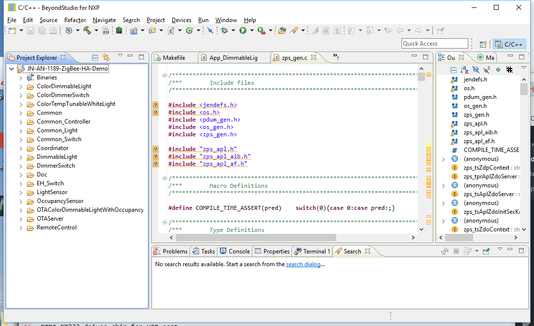
Now that your SDK and toolchain are installed download the ZigBee Home Automation Demo  (JN-AN-1189) from the NXP web site. Unpack and import it into your Eclipse workspace as an “Existing Project into Workspace” under the tab “General”. Yshould now have something like this on your screen:

Go to “Project” -> “Build Configuration” -> “Set Active” and select item #9 “DimmableLight 1 (DR1175)”. Then select “Project” -> “Build All” or just use the command line:

make LIGHT=DimmableLight DR=DR1175 REV=r1v1 all

The compile takes quite long but once finished you should have a binary “DimmableLight_JN5168_DR1175_LED_EXP_MONO.bin”. Plug your Meshbee on top of the UartSbee. Make sure SW3 of the UartSBee is in the “Prog” position and connect UartSBee with a USB cable to your computer.   In Eclipse select from the “Device” -> “Program Device”. Program you MeshBee with the freshly compiled firmware.
You can now use your ST app on your phone to add a new device. After a while, the MeshBee should show up as a “Thing” device. Rename it to something of your choosing and save it.
Head over to your ST development environment, login and check under “My Devices”. You should see you freshly added device listed under the name you assigned. Click on the name and you will get a page like this:

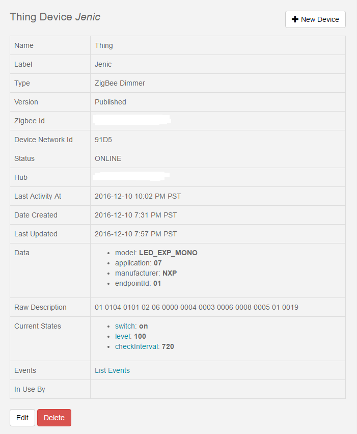
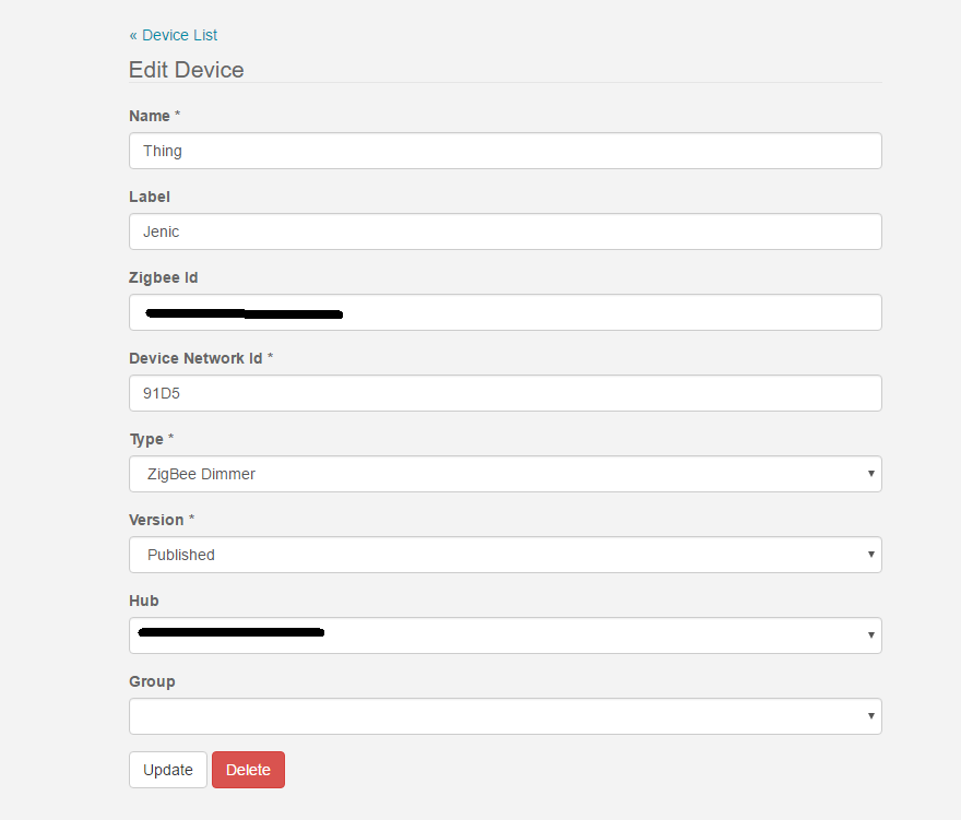
Now click on the Edit button and change the “Type” to “Zigbee Dimmer” and save it by clicking the “Update” button

You should now get a proper Tile in your ST App on your phone. Click on the On/Off button and in the log you should see events being logged. Connect a LED or Voltmeter to D13 and you can see the LED turn on and off.
This blinky example is the “Hello World” demonstration of a Zigbee actor connected to a Smartthings hub.

Temboo ignited with a Spark

This is a re-post of an article I wrote as a guest blogger for Temboo’s blog.
I am working with connected devices and was looking for a cloud service. While surveying the field Temboo caught my eye because of the large number of supported premium web sites and the promise to connect IoT devices to the Internet in a breeze.
spark_size The connected device I am using is a Spark Core. The Spark Core is a sleek small board that offers a powerful 32 bit ARM CPU paired with WiFi. The product grew out of a Kickstarter campaign and is rapidly gaining in popularity. The Spark is nicely priced and everything is open source. The team supporting the Spark Core is smart and supportive and made a great choice to port most of the main Arduino APIs to their platform.
As outline in a blog post here migrating Arduino Libraries to the Spark Core often turns out to be pretty easy. With Temboo providing an open source library for Arduino I was tempted to give it a try. However, I had no Temboo-Arduino setup so I was not sure how hard it would be to get it all up and running.
Well, I am happy to report that is was easier than expected. Temboo’s code is well written. I only had to work around some AVR specific optimizations that Temboo did to save program memory. As the Spark Core is built around a STM32F103 chip resources are not as tight as with the AVR so I simply bypassed these optimizations.
Here are some brief instructions how to install the Temboo Arduino Library. The instructions use the Spark command line SDK setup:

  1. Download the modified Temboo Arduino Library source code from github:
    mkdir temboo
    cd temboo
    git clone https://github.com/bentuino/temboo.git
  2. Get the Spark Core firmware:
    git clone https://github.com/spark/core-firmware.git
    git clone https://github.com/spark/core-common-lib.git
    git clone https://github.com/spark/core-communication-lib.git
    // Merge the two source codes
    cp -fr core-* temboo
    rm -fr core-*
  3. In older Spark firmware there is a small problem that the spark team already fixed. Open the file core-firmware/inc/spark_wiring_ipaddress.h and uncomment the line 54 with your favorite editor:
    // Overloaded cast operator to allow IPAddress objects to be used where a pointer
    // to a four-byte uint8_t array is expected
    //operator uint32_t() { return *((uint32_t*)_address); };
    bool operator==(const IPAddress& addr) { return (*((uint32_t*)_address)) == (*((uint32_t*)addr._address)); };
    bool operator==(const uint8_t* addr);
  4. Save your TembooAccount.h you generated with DeviceCoder to temboo-arduino-library-1.2\Temboo
  5. Now it is time to build the Spark application:
    cd temboo/core-firmware/build
    make -f makefile.temboo clean all
  6. Connect your Spark Core to your computer via a USB cable
  7. Push both buttons, release Reset button and continue holding the other button until RGB-LED lights up yellow
  8. Download application into Spark Core
    make -f makefile.temboo program-dfu

Temboo Examples

Two simple Spark application examples are included:

  • core-firmware/src/application_gxls.cpp – Example demonstrates the Temboo library with Google Spreadsheet
  • core-firmware/src/application_gmail.cpp – Example demonstrates the Temboo library with Gmail

to change the example that is built, edit the first line in the core-firmware/src/build.mk file:

CPPSRC += $(TARGET_SRC_PATH)/application_gxls.cpp

or

CPPSRC += $(TARGET_SRC_PATH)/application_gmail.cpp

Building this code was tested under Windows 8.1 using cygwin and the MINGW version of the ARM GCC compiler tool chain. It should be easy to use this Temboo Library with the Spark Cloud based SDK. To configure the Library to support Spark all the is required is to define the following label:

CFLAGS += -DSPARK_PRODUCT_ID=$(SPARK_PRODUCT_ID)

or add a

#define SPARK_PRODUCT_ID SPARK_PRODUCT_ID

to the source code. Temboo support for the Spark Core is a lot of fun. It is easy to setup your own Temboo account and compile the Temboo Arduino Library that now supports the Spark Core platform. To learn more about similar projects please visit my blog at http://bentuino.com.

Google polls Spark Core

appsIn a previous blog post I was describing an example of how a Spark Core can be used to read weather sensors. The setup was really no different from any simple Arduino Uno setup. It only demonstrated how easy it is to port Arduino Sketches to a Spark Core.
With the integrated WLAN I was interested to connect the Spark Core to the internet cloud. One of the simplest ways I found, was using Google’s Spreadsheet service. I stumbled over this idea in this Spark forum post.
Here is how it works: a Google Script is periodically reading data from the Spark Core via the RESTful Spark API and then appends the data to a Spreadsheet. The code below is a minimalistic Spark code to test the such a setup:

int variable = 1634;
void setup() {
  Spark.variable("variable", &variable, INT);
}
void loop() {
  variable++;
  delay(5000);
}

It publishes a variable for cloud access and then increments it in regular intervals. Together with the following Google script I was able to quickly pull data from my core.

function collectData() {
  var  sheet = SpreadsheetApp.getActiveSheet();
  var sensor = UrlFetchApp.fetch("https://api.spark.io/v1/devices/<id>7/variable?access_token=<token>");
  // parse the JSON the Core API created
  var sensor = JSON.parse(sensor.getContentText());
  // you'll need to unescape before your parse as JSON
  var sensor_result = unescape(sensor.result);
  // create a time stamp
  var d = new Date();
  // append data to spreadsheet
  sheet.appendRow([d, sensor_result]);
}

However when I setup a time trigger to run the script in regular intervals I found the setup to be very unreliable. This is discussed and documented by several Spark Users and as of this writing I have not seen a fix for this problem.
One thing to note is, that this approach is pulling data from the Spark Core rather than the core pushing them to the cloud. This has a significant flaw as we cannot put the core into standby between the measurement intervals. Therefore this solution is anyway not a good choice for low power applications.
So stay tuned, I am experimenting with a better solution that I will blog about in my next post.

Encounter with a Spark

I have tested several IoT platforms over the last couple of weeks. So I was not too keen to checkout yet another one. However, when I got the annoucement that the Spark Core is shipping I could not resist and ordered one. It arrive in the mail today so I thought I will take it for a spin.
The Spark Core comes in a very stylish little box.
Spark Box
Figure1: Spark Box
To my surprise the box did even includes a breadboard:
spark2spark3
Figure 2: Open Spark Core Box
Overall, the box contains the Spark Core board, a breadboard, a micro-USB cable and Spark sticker.
spark4
Figure 3: Box Content
It is amazingly simple to get the board up and running. By following these few simple steps:

  1. Download the Spark App for iPhone or Android
  2. Setup an account by register at spark.io
  3. Power up the Spark Core over the USB cable
  4. Start Spark App and log into your wireless network

If everything works well you will get rewarded with the RGB-LED on the Spark board flashing in rainbow colors. Once the Spark Core is connected to you WiFi and paired with the Spark cloud, it took me only a few minutes to get an on-board blue LED blinking.
It very quickly becomes obvious that the Spark team has done a great job setting up an entire end-to-end IoT solution consisting of:

  1. Spark Hardware
  2. Cloud based IDE
  3. Arduino compatible API
  4. Free for life cloud back-end service with a RESTful API

All the Spark Core software is open source. The board uses a CC3000 WiFi Module from TI combined with a 32-bit ARM Cortex-M3 powered STM32F103 from ST Microelectronics. The Spark team has come up with a nice integration of this hardware and the cloud server back end. It is based on the CoAP protocol specification and allows for an easy and energy efficient integrated IoT solution.
The cloud API offers over-the-air (OTA) firmware updating where the input can either be c/c++ source code or binaries. For those that don’t want to use Spark Builder, their cloud based IDE the web site also promises support for desktop IDEs like Eclipse.
So much for today, I will cover more details in future blogs.

Do you need WiFi Connectivity in your project?

There are a lot of WiFi solutions for Makers out there. However many are either expensive, big or outdated. So it is refreshing to look at the technical data of the little known WiFi module available by the name of RTX4100  from RTX Telecom. You may never have heard of RTX Telecom but this Danish design service company specialized in wireless has been around for many years.  The module is hardly bigger than a Bluetooth module.
RTX_BT1
Figure1: on the left a simple Bluetooth HC-5 module and on the right the RTX4100 WiFi Module.
The RTX41xx uses latest WiFi System in a Package (SiP) technology. It features a Nordic Semiconductors 32-bit ARM Cortex-M3  based low power microcontroller.  The WiFi is based on a AR41xx SiP from one of the leading WiFi chip manufacturer  Qualcomm – Atheros.
The 32-bit application processor is responsible for all the WiFi driver related duties. But an API allows to program custom application into the module. RTX calls the custom programs Co-Located Application or CoLA.  Besides the RTX4100 that offers 24 kBytes flash memory and 3 kBytes RAM for custom applications. RTX also offers a pin compatible RTX4140 that provides much more programmable memory for CoLA applications, 512 kBytes flash and 64 kBytes RAM.
CoLa
The SDK can be downloaded from RTX’s web site together with a comprehensive set of documents and CoLA examples.
On the Hardware side the module offers 30 solder pins that support a variety of  I/O functionality:

  • ADC ports, DAC ports
  • GPIO ports
  • UART, SPI, I2C
  • Timers

RTX has also teamed up with some cloud services. The currently supported cloud partners are: 2lemetryExositeNabto and Sensinode.
For simple applications like WiFi sensors or actors that require a limited set of IOs and CPU/Memory resources RTX41xx modules can be used stand alone. They are also a great choice for embedded projects based on Arduino that need WiFi.  Similar to some of the popular Bluetooth modules you only need a spare UART or SPI interface to talk to the RTX4100.
Unlike Electric Imp that offers you a fully integrated platform form the module all the way up to the cloud, RTX is a much more open and flexible platform where you retain control. However this control also comes at the price that you have to do more software work. The good news is that you don’t have to start from scratch, RTX supports you with quite a bit of Software.

Another IoT Platform – WICED

Broadcom is also jumping on the IoT wagon with the WICED  platform.  The platform is targeting Bluetooth and WiFi applications. The WiFi modules feature the BCM43362 WiFi chip integrated into a System in a Package (SiP) module. The Image below shows a WiFI WICED PCB module with a Murata WiFi SiP Module and a STM32F205 microcontroller. Murata also offers SiP modules that have the ARM microcontroller built in.
wiced_BCM943362WCD4
On the software side the platform is supported by a feature rich SDK and support for OSs:

  • WICED Application Framework including bootloader, flash storage API, over-the-air (OTA) upgrades, factory reset, and system monitor.
  • An open source build system and toolchain based on GNU make (native IAR support coming soon!).
  • A GUI Development Environment based on Eclipse CDT that seamlessly integrates with a JTAG programmer and single-step, thread-aware debugger based on OpenOCD and gdb.
  • A software stack with a choice of several RTOS/TCP stack options including ThreadX/NetXThreadX/NetX Duo and FreeRTOS/LwIP.
  • Support for security and networking features such as SSL/TLS, IPv4/IPv6 networking, and mDNS (Bonjour) device discovery.
  • Simple out-of-box device setup using Apple-licensed MFi technology or via a web browser and softAP/web server.

Broadcom also make a set of software examples available that help getting started quickly:

  • Production ready sample applications.
  • Lots of application snippets demonstrating how to use the rich WICED API feature set.
  • Various test applications to aid manufacturing and certification.
  • All documentation included inside the WICED SDK.

The next Electric Imp

Yesterday evening Hugo Fiennes, CEO and Co-founder of Electric Imp gave a talk at the Mountain View Hacker Dojo.
Hugo did a great job explaining the Electric Imp platform to a packed room. Besides a M&M candy dispenser that he controlled over the internet he also brought a board with the next generation Electric Imp on it.
20140129_201910
The Electric Imp is the silver module on the left. The tiny size gives an idea of how small of a form factor internet connectivity will be available. Hugo also shared his excitement about the reduction in power consumption and the ability to power IoT devices from batteries.

First Steps with the Electric Imp

At the CES 2014 Intel announced the Edison platform that is intended to enable IoT applications.  As pointed out in my earlier blog, there is a pretty similar solution out there. It goes by the name of Electric Imp.
El_Imp
cloudgraphic
The Electric Imp is a platform that consist of several parts:

  • The SD-Card size Electric Imp
  • A web based IDE
  • A cloud service that integrates with the Electric Imp hardware
  • The BlinkUp cell phone app to pair the Imp Hardware with your local network and Electric Imp web services

Such an impressive combination promised some fun, so I was curious how well all the components would work together.  To try it out I got myself an Electric Imp and the related Imp Arduino Shield from Sparkun. In order to use it with Arduino Shields or Arduino Boards you have to also order the headers and solder them on the board. I use the Arduino Stackable Header Kit . The stackable header allow you to use the Imp as a “WiFi Shield” to an Arduino Single Board Computer (SBC) as well as being a standalone SBC. If you only use you Electric Imp as a SBC you won’t need any stackable headers. Also make sure you order the headers that fits your Arduino board. There are different revisions out there. The R3 version has additional pins and will not fit an original Arduino board.
Once the headers are soldered down you can plug the Electric Imp Shield on top of an Arduino board. Signup for an account on http://electricimp.com and download the BlinkUp app to your smartphone. Fire-up the app and log into your Electric Imp account with your credentials. It’s time to power up the Arduino-Imp combo. Hold your Phone screen flush with the front edge of the Electric Imp card and start the pairing process. The phone screen flashes for a while. Once the flashing stops the Electric Imps status light should turn green. You can get detail instructions on the Electric Imp web site or on Sparkfun. So far not a lot of challenges.
Time has come to whip together some code that brings this combo to life. To test the Electric Imp I used some modify code from their web site.

// create a global variabled called led,
// and assign pin9 to it
led8 <- hardware.pin8;
led9 <- hardware.pin9;
// configure led to be a digital output
led8.configure(DIGITAL_OUT);
led9.configure(DIGITAL_OUT);
// create a global variable to store current
// state of the LED
state <- 0;
function blink() {
  // invert the value of state:
  // when state = 1, 1-1 = 0
  // when state = 0, 1-0 = 1
  state = 1-state;
  // write current state to led pin #8
  led8.write(state);
  // schedule imp to sleep for .5 seconds.
  imp.sleep(0.5);
  // write current state to led pin #9
  led9.write(state);
  // schedule imp to wakeup in .5 seconds and do it again.
  imp.wakeup(0.5, blink);
}
// start the loop
blink();

The code above let’s the two LEDs on the Electric Imp Shield blink alternatively for half a second each. So if you see the LEDs blinking, you know that the IDE properly compiled it and downloaded it over the internet into the Electric Imp card where it gets properly executed. Well Done! Stay tuned, in my next installment I will try to get the Electric Imp talk to the Arduino.

Is Edison competing with Galileo

Last summer at the Maker Fair in Rome Intel announced the Galileo single board computer . This week at CES 2014 in Las Vegas Intel followed up with another initiative that carries an inventors name. This time it is Edison. The Edison board is more advanced take on the Quark System on a Chip (SoC) based single board. The board is only the size of an industry standard SD card. So don’t expect to solder it yourself.
edison
However the card is a full featured single board computer that will offer support for multiple operating systems (OS).  The integrated WiFi will turn any device equipped with an Edison into an IoT solution.
Intel also promised to release design files that will make it easy to  integrate Edison into your own project.  Among the tool vendors that will support Edison is Autodesk. The company just announced the  acquisition of circuit.io. This online PCB design tool is now a part of Autodesk’s 123D design suite.
For those that cannot wait and want something today the Electric Imp Wireless SD-CARD is an interesting alternative. This card is clearly not as powerful as an Edison. However given the creativity that innovators have displayed around the meager Arduino 8-bit AVR CPU  it may still be plenty.
El_Imp